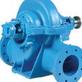
Grundfos’ PACO KP split-case, double-suction pump. Photo courtesy of
Grundfos
This four-part series of articles is intended to explain and develop the basic principles of pump operation and, except for sizing, allow the optimum selection of centrifugal pumps.
This section concentrates on centrifugal pumps. The following conditions are used for purposes of discussion only:
- Internal pump losses will be ignored.
- Water will be used as the liquid.
- Only single-stage, open systems will be discussed.
- This section is limited to commercial products that are easily available.
A centrifugal pump is a nonpositive displacement, dynamic machine that transfers mechanical energy into a practical and useful form called pressure. The pump first converts this energy from water into velocity with a circular (centrifugal) force and then into head or elevation (pressure energy) as it passes from the eye of the pump, through the impeller and finally through the casing and volute. A typical centrifugal pump is illustrated inFigure 1.A schematic illustration of the flow pattern of water inside a pump when spun by the impeller is illustrated inFigure 2.
In basic terms, a centrifugal pump’s performance is measured by a volume of delivery against how high it will lift a column of water, with consideration given to its efficiency. The flow of water is almost always designated as foot of head vs. gallons per minute because this gives the best general description of pump operation. Refer toTable 1below on for a conversion of various quantities into U.S. gpm.
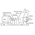
Figure 1.
Key Pump Definitions
Affinity laws.The affinity laws describe the relationships between capacity, head, brake horsepower and impeller diameter for any particular pump. Capacity, head, net positive suction head (NPSH) and horsepower change as a result of speed change. Capacity, head, NPSH and horsepower change as a result of impeller diameter change.The relationships are:
1.Pump gpm varies directly as a change of impeller speed or impeller diameter ratio.
2.Pump head and NPSH vary directly as the square of speed or impeller diameter ratio.
3.Pump horsepower varies directly as the cube of the speed or impeller diameter ratio.
Best efficiency head (BEH)is a reference point where the pump operates at about 80% to 90% of the shutoff head only with regard to the shutoff head displayed on the general pump curve. The pump head is shown by convention on a vertical scale at the left side of a manufacturer’s pump graph. This is a general rule and not a law.
Best efficiency point (BEP).The best efficiency point is a term that can be defined in several ways. The one most often used is a general term applicable to all pumps that occurs when the operating condition of a generic pump design has it highest efficiency. The second is for a specific pump that has its theoretical BEP where the incidence angle of the fluid entering the hydraulic passages best matches with the vane angle of the impeller. The third is where the system curve and pump curve for a specific application intersect. A general rule (not a law) is to have a pump operate at about 85% of the shutoff head using the system curve as reference.
Cavitation.This occurs when the atmospheric pressure acting on a liquid is below its vapor pressure, causing it to boil and create bubbles. When bubbles in the liquid pass into a region of lower pressure they collapse or implode with a resulting shock wave that could cause damage to any interior, wetted surface.

Figure 2.
Efficiency.Expressed as a percentage, efficiency is the ratio between the total possible output power developed by the motor of the pump compared to the actual input power supplied to the pump, taking into consideration the losses due to heat, vibration, internal friction, distortion and noise. Simply put, a pump’s peak efficiency is the point where it does the most work for the least input energy. The efficiency is dependent upon the impeller and volute design and indicates a point where minimum turbulence is encountered. The efficiency is determined by tests done by the manufacturer.
Entrance and exit head losses of the pump.This refers to the friction lost, measured in foot head, at the entrance point of water into the supply pipe of the pump from a water supply. Water from a public main should not be calculated. This supply does not have any pump entrance loss, but rather, the entrance loss into the supply piping will affect the available NPSH.
Friction head.The complete frictional head loss, in foot head, that is needed to overcome the resistance of the liquid flowing in the supply piping. It is the sum of the supply pipe friction losses of the pipe walls, meter assembly, BEP, fittings, valves and suction pipe entrance losses. This head varies with the flow, size pipe and character of the liquid pumped. Note: This figure is not to be used for the calculation of the head necessary for the required design head for pump calculations.
Non-overloading characteristic.This is where the driver of the pump is not overloaded under any operating condition. As with most centrifugal pumps, a higher horsepower motor will prevent overloading under all conditions of pump operation. To achieve this, the operating point is placed on the impeller diameter curve and the horsepower curve is plotted above that point, but will not intersect it.
Open system.This type of system is characterized by having a point of free discharge, such as water supply to a house tank or a cooling tower.
Theoperating pointis shown on the graph of the performance curve of the pump and is the intersection of the system curve and the performance curve. In the absence of a system curve, the operating point is placed directly on the impeller diameter of the selected pump.
Overloading.Overloading occurs when the flow increases and the BHP increases to a maximum. There must always be enough horsepower available from the driver to supply the needs of the pump. As the total dynamic head (TDH) falls, the flow increases and so does the BHP, which will overload the driver.
Pump curve.This curve, often called the “H-Q” curve, is a downward sloping plot showing the actual well-defined relationship between flow rate and total foot head for a typical, characteristic pump made under carefully controlled conditions. The curve is established by the pump manufacturer. It starts with the shutoff head where all the pump’s energy is invested in elevation with zero flow and ends when all the energy is invested into maximum flow with zero head. This relationship is unaffected by water temperature and water density. The “H” refers to total head and the “Q” is the flow in gpm. The pump curve permits the use of the system curve as a method of pump selection.
Pumping head(often referred to as total head) is the sum of all pressure requirements necessary for proper system operation.
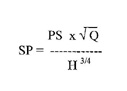
Specific speed.Specific speed is a dimensionless design index number primarily used by pump designers. The specific speed has no practical significance to the consulting engineer. Some manufacturers disagree concerning the usefulness of this figure at all.
The specific speed can be calculated usingthe equation to the right.
Where:
SP = Specific speed of pump, dimensionless
PS = Pump speed, in rpm
Q = Pump capacity at the BHP, in gpm
H = Pumping head at the BHP, in feet
A generically accepted range is from 500 to 15,000. The lower the speed, the higher the head.
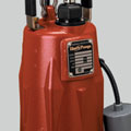
Liberty Pumps’ LEH150 sewage pump.
Photo courtesy of Liberty Pumps
Static head.This is the vertical difference, in feet, between the highest liquid-free discharge level and the free level of the supply source, which is the eye of the impeller with no liquid flowing. This also must include the addition or subtraction of the pressure difference of the suction or discharge source, whichever applies.
Suction head.This term is used when the supply is pressurized or the level of a body of water is higher than the centerline of the pump inlet (eye of the impeller).
Suction lift.This term is used when the supply is lower than the centerline of the pump inlet. The pump must lift water up into the eye of the impeller.
System curve.Often called the pump performance curve, this curve is simply a plot of the change of foot-head energy resulting from a flow change in a specific fixed piping system. The system curve starts at zero flow and zero head. It is an upward sloping curve of the actual operating conditions for a specific pump. The original point indicating flow and head requirements is first developed by the engineer and the full curve is extended both ways by the manufacturer from the original point. Since foot head is an expression of energy, a pump curve defined by this term is not affected by water temperature or density.
System head.A graphical representation of the total measure of energy, in foot head, imparted to a liquid for a specific pump at a specific operating speed and capacity. It is frequently used to refer to pumping head. By convention, the pump head is shown on a vertical scale at the left side of a manufacturer’s pump graph.
Vapor pressure.The absolute pressure of a given liquid that is required to keep it in the liquid state at a given temperature.
Velocity head.Two methods of measurement are used. The first is where the liquid is at rest. The velocity head is the energy needed to accelerate the liquid from a static start, measured in foot head, at the end of the discharge pipe.
The second is if the liquid is moving, and it is equivalent to the vertical distance in foot head, then the mass of liquid would need to fall to attain the same velocity as the liquid traveling in a pipe. Because it is a required force to accelerate the liquid at the origin of the system, it is subtracted from the suction head or added to the suction lift. The velocity head is a factor in calculating the total head, although this value is usually quite small. This head is entirely lost if the discharge pipe is the same size as that of the supply pipe.
Bell
& Gossett’s VSX centrifugal pump. Photo courtesy of Bell & Gossett
Conversion Factors For U.S. GPM (Table 1)
Given Unit Equiv. U.S. GPM1 pound per minute 0.12
231 cubic inches per minute 1
1 cubic foot per minute 7.481
1 cubic foot per second 448.8
1.000 pounds per hour 2
1 imperial gallon per minute 1.2
1 million gallons per 24 hours 695
1 barrel of oil per minute 42
100 barrels per hour 70
100 barrels per 24 hours 2.92
1 liter per minute 0.2642
1 liter per second 5.852
100 liters per hour 0.44
1 cubic meter per minute 264
1 cubic meter per hour 4.4
1 acre foot per minute 326,000