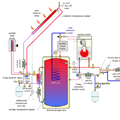
Figure 1.
Several design principles apply to solar thermal combisystems. The first, and perhaps most important, is to keep the collector inlet fluid temperature as low as possible. This decreases heat loss from the collectors and boosts their thermal efficiency.
A second design principle indirectly related to the first is to avoid using the auxiliary heat source to maintain some working temperature in the solar storage tank. Doing so delays the startup of the solar collection system when the sun returns, and thus decreases total energy collected relative to a system starting up with a “cooler” storage tank.
The ability to execute the second design principle depends on two issues:
1.Does the system use the same auxiliary heat source for both space heating and domestic water heating?
2.Does the system use the thermal mass of the storage tank to buffer a zoned space-heating distribution system?
Let’s examine some options based on these issues.
Figure 1 shows a system that uses two auxiliary heat sources, one for space heating and another for domestic water heating. The auxiliary heat source for domestic water could be a standard DHW storage tank, a tankless heater or another approved, thermostatically controlled device that can “top off” the domestic water to the required supply temperature as necessary. The auxiliary heat source for space heating could be a boiler or a heat pump. Its function is to provide the heat necessary to supply the space-heating load when heat from the solar storage tank cannot.
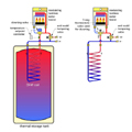
Figure 2.
As it leaves the coil, the fully heated domestic water must pass through an auxiliary water heater. However, the thermostatically controlled heating element or burner in this auxiliary water heater would remain off. The fully heated water from the coil is just “passing through.” It continues on the hot port of an anti-scald-rated thermostatic tempering valve before heading to the fixtures. This valve is an absolutemust in any solar water-heating system or combisystem. It protects against the possibility that water leaving the preheating coil could be very hot during sustained sunny weather.
If a modulating tankless water heater serves as the auxiliary water-heating device, the piping can be modified as shown inFigure 2. This arrangement diverts the fully heated water around the tankless heater to avoid starting its burner, which is usually controlled by a flow switch. This arrangement also eliminates the unnecessary heat loss that would occur by passing heated water through the piping and other components in the tankless heater.
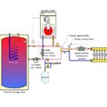
Figure 3.
Three-Way Calling
In some systems, a second three-way thermostatic valve is used for the diverting function in lieu of a motorized valve and temperature set-point controller. This arrangement is shown in Figure 2. It works well provided the thermostatic diverter valve has a relatively narrow proportional operating range. Some manufacturers now offer this dual thermostatic valve arrangement as a preassembled module.The three-way motorized diverting valve seen to the right of the storage tank allows cooler water returning from the space heating distribution system (and entering port AB of the diverter valve) to pass into the storage tank (existing port B of the valve) or be diverted to the inlet of the auxiliary boiler (exiting port A of the valve).
The decision on which way return flow is routed is made by an outdoor reset controller, which measures both the temperature at the top of the storage tank and the outdoor temperature.
This controller is set to calculate the minimum acceptable water supply temperature for the space-heating system. If it determines the water in the storage tank is at or above this temperature, flow is routed through the tank, making it the heat source for space heating. If the tank’s water is not warm enough to supply space heating, the diverter valve changes position to route flow through the boiler. It would also close another electrical contact to enable the boiler to operate. The same circulator that created flow through the storage tank provides flow through the boiler.
Under this condition, the storage tank is totally isolated from the space-heating distribution system. The tank’s temperature will continue to drop due to flow of domestic water through the coil and heat loss through the tank’s insulation. Assuming the tank is located in heat space - which is highly recommended - the latter heat loss still contributes to space heating. If there are several cloudy days in a row, the tank’s temperature will eventually “coast” down toward room temperature. The low-grade heat leaving the tank under such conditions is still contributing to space heating and the preheating of domestic water.
As such, each Btu released from the tank is displacing a Btu of auxiliary energy. When the sun re-emerges, the collector subsystem will turn on as soon as the collectors are a few degrees warmer than the cool water at the bottom of the storage tank. This scenario is a classic exploitation of low-temperature heat - agoodthing.
Flow diverting through the tank vs. the boiler also can be handled using two “toggled” circulators as shown inFigure 3. One circulator operates when the tank serves as the heat source, the other when the boiler serves as the heat source. This may be a less expensive option in larger systems with higher flow requirements. It also allows each circulator to be selected for the flow and head loss requirements of its respective circuit.
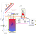
Figure 4.
Efficient Design
The combisystem schematic shown inFigure 4uses drain-back freeze protection of the collector array. The air space at the top of the storage tank serves as the drain-back reservoir, as well as the system’s expansion tank. Notice that there is no automatic make-up water subsystem. It’s not needed. The vast majority of the water and air added during installation remains in thisclosed loopsystem throughout its life. Any minor water losses through valve packings, circulator gaskets, etc., can be monitored by the sight glass on the collector supply pipe. Any needed make-up water can be added through the hose bib valve in the collector piping.This combisystem uses a single auxiliary boiler, when necessary, forbothspace heating and domestic water heating. The temperature of the water at the top of the storage tank is continually maintained at a suitable minimum value sufficient to supply domestic hot water when the domestic water makes a single pass through the coil.
This arrangement eliminates the need for a separate auxiliary heater solely for domestic hot water. It also allows the upper portion of the storage tank to serve as a buffering thermal mass for the zoned distribution system. This is another good thing.
The motorized diverter valve directs flow through the boiler only when necessary to maintain the temperature of the tank. The control logic is again based on outdoor reset control, but it is not directly (electrically) tied to operation of the distribution system. Boiler operation is only based on maintaining a suitable minimum temperature in the upper portion of the buffer tank.
The compromise is that this design violates the design principle of not using auxiliary energy to maintain the temperature of the storage tank. The key to minimizing the influence of this compromise is good temperature stratification in the storage tank. Such stratification will be affected by the tank’s dimensions, as well as where the piping connections are made. The goal is to keep the lower portion of the tank relatively undisturbed by flow and temperature in the upper portion of the tank.
Comparing The Systems
So which approach is better? It’s hard to say. The system shown in Figure 4 is simpler, and likely to cost less than the system in Figure 1. It provides good buffering of the zoned distribution system, which is very important, especially in low energy-use houses.There are two possible ways to see if the installation cost savings associated with the system in Figure 4 would be more than offset by slightly lower solar energy gain due to maintaining the top of the storage tank at a minimum temperature:
1. Build each system in the same location and at the same size. Subject each system to identical loading. And monitor the auxiliary energy usage of each system.
2. Develop a very detailed computer simulation model that could assess tank stratification and factor its influence into overall system performance. I was involved in similar computer modeling many years ago. It’s very interesting from a theoretical standpoint, but very time consuming, and only as accurate as the assumptions used.
Neither option is a simple or an inexpensive undertaking. So, like many of the different approaches now used in solar thermal combisystems, I suspect the choice of systems will be made based on other factors such as available space, desire for simplicity, the type of space-heating distribution system used, and, perhaps most important for the customer, the capabilities, reputation and sales skills of the firm proposing the installation. That’s also a good thing.
