There have been significant changes to NFPA 13,Standard for the Installation of Sprinkler Systems, between the 2002 edition and the 2007 edition. This article series addresses the major technical changes that are contained within the 2007 edition of NFPA 13 relating to seismic protection of automatic sprinkler systems.
The 2007 edition made specific seismic changes in nine specific areas. The first five of these areas were discussed in detail inPart 1 (Jan. 2009), with the final text of NFPA 13 included in quotation marks (indented paragraphs). InPart 2, we discuss areas six and seven.
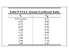
See “Table 9.3.5.6.2
Seismic Coefficient Table”.¹
6. Horizontal Seismic Loads
The determination of horizontal seismic loads has been modified in four main areas. First when determining the weight of the system being braced (Wp) the weight shall be 1.15 times the weight of the water filled pipe to account for system components such as valves, hangers and fittings (Section 9.3.5.6.1). Secondly, the horizontal force due to seismic loads (Fpw) acting on the brace at working stress levels, is now a function ofSsfor the building location as described in the annex. The ground motion parameterSswhich is defined by NFPA 13, Section 3.11.7 is the Maximum Considered Earthquake Ground Motion of 0.2 sec Spectral Response Acceleration (5 percent of Critical Damping), Site Class B for the site.Ssis then utilized in Table 9.3.5.6.2 to relate to a value ofCp, which is a new seismic coefficient defined in Section 3.11.6 as the combination of the ground motion and seismic response factors from ASCE 7, for the equationFpw = CpWp(Section 9.3.5.6.2). Thirdly, where the Authority Having Jurisdiction does not specify a horizontal seismic load the force is determined utilizing aCp= 0.5 (Section 9.3.5.6.3), which relates to 1/2Wpand is consistent with previous editions of NFPA 13. Finally, the zone of influence for each lateral brace includes all the branch lines and mains tributary to the brace, unless the branch lines are provided with bracing (Section 9.3.5.6.4).- 9.3.5.6* Horizontal Seismic
Loads.¹
9.3.5.6.1* The horizontal seismic load for the braces shall be as determined in 9.3.5.6.4 or 9.3.5.6.5, or as required by the authority having jurisdiction. The weight of the system being braced (Wp) shall be taken as 1.15 times the weight of the water-filled piping. (See A.9.3.5.6.1.) ¹
A.9.3.5.6.1 The factors used in the computation of the horizontal seismic load should be available from several sources, including the project architect or structural engineer or the Authority Having Jurisdiction. In addition, the ground motion parameter Ss, is available using maps or software developed by the U.S. Geological Survey. The approach presented in NFPA 13 is compatible with the requirements of SEI/ASCE 7, Minimum Design Loads for Buildings and Other Structures, which provides the seismic requirements for model building codes. Sprinkler systems are emergency systems and as such should be designed for an importance factor (Ip) of 1.5. Seismic load equations allow the reduction of the seismic force by a component response modification factor (Rp) that reflects the ductility of the system; systems where braced piping is primarily joined by threaded fittings should be considered less ductile than systems where braced piping is joined by welded or mechanical type fittings. In addition, a @ factor, is used to account for dynamic amplification of nonstructural systems supported by structures. Currently, steel piping systems typically used for fire sprinklers are assigned an Rp factor of 4.5 and an @ factor of 2.5.1
9.3.5.6.2 The horizontal force, Fpw, acting on the brace shall be taken as Fpw = CpWp , where Cp is the seismic coefficient selected in Table 9.3.5.6.2 utilizing the short period response parameter Ss. The value of Ss used in Table 9.3.5.6.2 shall be obtained from the AHJ or from seismic hazard maps. Linear interpolation shall be permitted to be used for intermediate values of Ss.”¹
See “Table 9.3.5.6.2 Seismic Coefficient Table”.¹
- “9.3.5.6.3* Where the Authority Having Jurisdiction does not specify
the horizontal seismic load, the horizontal seismic force acting on the braces
shall be determined as specified in 9.3.5.6.2 with Cp = 0.5.1 A.9.3.5.6.3 Ss is a measure of earthquake
shaking intensity. Ss
shall be taken as the Maximum Considered Earthquake Ground Motion for 0.2
sec Spectral Response Acceleration (5 percent of critical damping), Site Class
B. The data are available from the AHJ, or in the United States, from maps
developed by the U.S. Geological Survey. All that is required to get Ss is the latitude and longitude
of the project site. The horizontal force factor was given as Fp in earlier editions of NFPA
13. It has been changed to Fpw, to clearly indicate that it is a working, not an
ultimate, load. In model building codes, Fp
is used to denote the strength design level load.¹
9.3.5.6.4* The zone of influence for lateral braces shall include all branch lines and mains tributary to the brace, except branch lines that are provided with longitudinal bracing.¹
A.9.3.5.6.4 The zones of influence do not have to be symmetrically based on brace spacing. It is the intent of NFPA 13 that the chosen zone of influence be the worst-case load scenario.¹
9.3.5.6.5 The zone of influence for longitudinal braces shall include all mains tributary to the brace.”¹
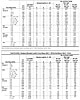
Table 9.3.5.8.8(a) and Table 9.3.5.8.8(b)
7. Maximum Allowable Brace Loads
Tables 9.3.5.8.8(a), (b), (c) provide maximum allowable loads for sway braces depending on the brace shape and size and the appropriate maximum l/r (100, 200, or 300). These tables were updated to ensure that each table accurately represented the maximum limits depending on the material chosen.- “9.3.5.8.8* The loads determined in 9.3.5.6 shall not exceed the
lesser of the maximum allowable loads provided in Table 9.3.5.8.8(a), Table
9.3.5.8.8(b), and Table 9.3.5.8.8(c) or the manufacturer’s certified maximum
allowable horizontal loads for brace angles of 30 to 44 degrees, 45 to 59
degrees, 60 to 89 degrees, or 90 degrees.”¹
See “Table 9.3.5.8.8(a) Maximum Horizontal Loads for Sway Braces with l/r = 100 for Steel Braces with Fy = 36 ksi”.¹
See “Table 9.3.5.8.8(b) Maximum Horizontal Loads for Sway Braces with l/r = 200 for Steel Braces with Fy = 36 ksi”.¹
See “Table 9.3.5.8.8(c) Maximum Horizontal Loads for Sway Braces with l/r = 300 for Steel Braces with Fy = 36 ksi”.¹
- ”9.3.5.8.9* Other pipe schedules and materials not specifically
included in Table 9.3.5.8.8(a), Table 9.3.5.8.8(b), and Table 9.3.5.8.8(c)
shall be permitted to be used if certified by a registered professional
engineer to support the loads determined in accordance with the above criteria.
Calculations shall be submitted where required by the Authority Having
Jurisdiction.¹
A.9.3.5.8.9 Maximum allowable horizontal loads for steel sway braces shown in Table 9.3.5.8.8(a), Table 9.3.5.8.8(b), and Table 9.3.5.8.8(c) are applicable when the system is designed using allowable stress design methods. The maximum allowable loads have been derived for the controlling condition (braces in compression) using American Institute of Steel Construction Manual of Steel Construction, Allowable Stress Design (9th Edition), Equations E2-1 and E2-2, and taking a one-third increase in design stresses as allowed for seismic loads per Section A.5.2 of that document. In determining allowable horizontal loads in the tables, a modulus of elasticity (E) of 29,000 ksi, a yield stress (Fy) of 36 ksi, and an effective length factor (K) of 1.0 were assumed, since these are common. If these values are different in a specific situation, table values might need to be adjusted. Gross section properties are used for all shapes except for all-thread rods. For all-thread rods, area and radius of gyration are based on the minimum area of the threaded rod based on the radius at the root of the threads.”¹
References
1.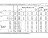
Table 9.3.5.8.8(c)
Series Summary: A Quick Review of Part 1
This sidebar is intended to providepmereaders with a better context in which to readPart 2of this article series.Part 1 appeared in the Jan. 2009issue and covered five specific areas (listed below) of the 2007 edition of NFPA 13. Among the highlights:1. Flexible Sprinkler Hose Fittings
While on the surface the new requirements for the use and installation of flexible sprinkler hose fittings does not appear to have an impact on seismic design, the committee provided additional annex material addressing the potential benefit of utilizing flexible sprinkler hose fittings in seismic areas due to their ability in providing the necessary deflection under seismic conditions.
2 . Obstructions to Sprinklers
Where bracing and restraint is added to mains and now in some cases to branch lines, there is a possibility that if either the brace or the restraint is located too close to the sprinkler it will obstruct the discharge of the sprinkler and, therefore, the obstruction rules of Chapter 8 apply in specific cases.
3. Flexible Couplings
Two specific areas requiring flexible couplings were added or modified to address flexible couplings for floor tie-ins and for drops to hose lines, rack sprinklers, and mezzanines. Section 9.3.2.3(2) was modified to address the location of flexible couplings where a floor tie-in does not incorporate a riser and where the tie-in is horizontal only.
4. Seismic Separation Assemblies
For the 2007 edition the committee has expanded its requirements and allowances for seismic separation assemblies. Figure A.9.3.3(b) was added to address an example of the new allowance for the use of flexible piping in lieu of a series of pipe, fittings and couplings.
5. Lateral Sway Bracing
The biggest area of change for the 2007 edition involves the spacing criteria of lateral braces. These changes were needed to ensure that NFPA 13 met or exceeded the design requirements of ASCE 7-05,Minimum Design Loads for Buildings and Other Structures.