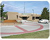
Fountain at City Hall, Grandview, MO. (Sioux Chief photo)
Case Study I
A recent case study involved a severe water hammer problem in a fountain refill piping system at the City Hall Building in Grandview, MO (a suburb of Kansas City). The system consisted of a long run of 1-1/2" copper tubing leading up to a solenoid valve in a utility room within the city hall building itself. On the non-pressure side of the valve, 1-1/2" PVC piping exited the building underground and ran 100 feet to the fountain pool outside. A float switch in the pool controlled the solenoid valve back in the utility room. No other valves, before or after, were being operated. Each time this valve cycled off, a large bang emanated from the valve and echoed throughout the building.Previously, the city hall maintenance engineer had a water hammer arrester installed on the pressure side of the valve. Proper installation requirements for sizing and placement of the arrester were followed. However, the arrester seemed to have little effect on the loud hammer upon each valve closure. Eventually, the destructive water hammer created a large crack in the PVC threaded adapter on the non-pressure line, six feet downstream of the valve, causing a noticeable leak inside the utility room.
A local plumbing contractor, Morgan-Miller Plumbing, was then called in to analyze the situation and fix the problem. At first, this fitting failure was a bit puzzling. Under normal water hammer situations, one would naturally expect the failure to occur on the pressure side of the valve. That's why arresters are usually required on the pressure side of valves. But in this case, the arrester was found to be working just fine, with no significant pressure surges upstream of the valve. This failure was definitely on the downstream side of the valve.

Figure 1. Cole D'Andrea, Morgan Miller Plumbing, installs a vacuum arrester at Grandview City Hall. (Sioux Chief photo)
Cavitation occurs when water pressure is lowered below its vapor pressure. Water will literally flash or vaporize, forming small entrained bubbles (water vapor in its gaseous state) in the line directly after the quick closing valve. In situations like the City Hall piping system, three factors play a role in this cavitation; high velocity, pipe length, and quick valve closure. When the valve closes, the momentum of flow pulls a vacuum on the area immediately after the valve, constricting the pipe. If the velocity is high enough, the water column can cavitate.
If you have ever done any pressure surge calculations, you may recognize the same three factors that cause water hammer on the pressure side of the valve are the same factors that can cause cavitation on the non-pressure side.That's not a coincidence. The momentum energy in the flowing water is equal on both sides of the valve. When a valve is installed in the middle of the piping run rather than the end, the non-pressure run will contain a significant amount of kinetic energy as well.
It is important to note that water temperature is certainly an essential factor in the physics of cavitation and the vapor pressure of water. Hot water will flash to vapor easier than will cold water. However, in this City Hall case, and in most other plumbing-related cases studied, the cavitation problems developed in an ordinary cold water piping system where temperature control or temperature change was not a factor.
The damaging effects of cavitation occur when momentum of the flowing water is dissipated and the entrained vapor bubbles collapse back to their liquid state. The rest of the non-pressure water column is then drawn back to fill this void at a super high velocity. An extremely high pressure surge (water hammer) results after the high velocity water column slams into the valve (Figure 2). In lab tests of similar piping arrangements, pressure surges caused by cavitation have been measured up to 1,100 psig.
A water hammer arrester installed on the pressure side of the valve works great to control the energy in the water column upstream of the valve, but does nothing to prevent the cavitation and severe pressure surge on the downstream side. Even installing a second water hammer arrester after the valve will not help, because conventional arresters are not designed to prevent this specific problem or to absorb the resultant shock.
A unique product called avacuum arresterwas introduced a few years ago to control this problem of cavitation. Similar in design to a piston-style water hammer arrester, the vacuum arrester temporarily breaks the vacuum that is pulled just beyond the closing valve. The operation of a vacuum arrester is functionally opposite of a conventional water hammer arrester.
The vacuum arrester has a much lower charge and the piston starts high in the barrel and travels down. When installed directly after the valve, the air in the vacuum arrester will expand to allow a more gradual stop of the water flow, and, thus, prevent cavitation.
In the Grandview City Hall piping system, the contractor correctly diagnosed the problem, installed a vacuum arrester, and repaired the cracked fitting. Once a vacuum arrester was installed in addition to the water hammer arrester, the fountain system operated safely and quietly without any damaging pressure surges on either the pressure side or non-pressure side of the valve.
Unlike common atmospheric vacuum breakers, a vacuum arrester employs a contained pressure chamber that will never spit or leak water, nor will it ever allow air to be introduced into the water line. However, a vacuum arrester is not a traditional backflow prevention device and should not be substituted for one in other applications where those devices are required by code.
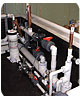
Figure 2. Vacuum arresters and water hammer arrester on both sides of the valve at Children's Museum water feature, Evansville, IN. (Photo courtesy of Randy Hinderer, Roto Studio)
Case Study II
A vacuum arrester was also the solution for an interactive water fountain at the Children's Museum in Evansville, IN, designed and installed by Roto Studio Co. Based in Dublin, OH, Roto Studio specializes in the design and production of unique interactive water features for museums and entertainment venues. Here again, an installed arrester on the pressure side did not solve the problem.Quite similar to the piping arrangement in the Grandview City Hall system, the culprit control valve was installed in the middle of a long pipe run. In this system, children were able to turn the water on and off from a remote switch in the fountain area, which resulted in the same problems with cavitation. Not only did the cavitations cause excessive noise, major failures occurred in several large PVC fittings on the non-pressure side within a short period of time.
Once cavitation was found to be the culprit issue, vacuum arresters were installed on each of the two non-pressure lines after the valve, and the problem was permanently solved. Vacuum arresters were then specified by Roto Design for all future projects.
This type of cavitation is certainly not isolated to large commercial or industrial piping systems. It can even happen in certain residential fixture applications, such as high-flow Roman tub valves or large shower valves. The problem will most likely never occur when the tub spout is installed in its traditional place between the valves.
However, a common design practice in recent years is to place the tub spout or shower head on the opposite side of the fixture from the control valves, thus creating a long non-pressure piping run. If the flow velocity is high enough, a cavitation can occur. To prevent this, a vacuum arrester should be installed on the non-pressure tub spout line or shower riser line, directly after the control valves.
One of the largest fixture manufacturers in the country now requires the installation of a vacuum arrester on the tub spout line for their high-flow tub valves to prevent problems associated with cavitation. Thousands of vacuum arresters have been successfully installed in single-family homes and high-rise hotels throughout the country over the past few years. Its simple design, low cost, and dependability make the vacuum arrester a great solution to this problem.