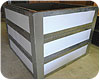
Figure 1. Courtesy of American Solartechnics.
In the June 2009Solar Design Notebookcolumn, we discussed the benefits of drainback systems. This month we’ll start looking into the system design details.
As is true with hydronic heating, solar drainback systems can be created as either open-loop or closed-loop configurations. Each approach has its strengths and limitations.

Figure 2.
Two Configurations
Open-loop design can be used for either solar DHW systems or solar combisystems. The latter supply heat for both hot water and space heating, and often require storage tank volumes of several hundred gallons. In such systems, the cost per gallon of a non-pressurized tank operated as an open-loop system is often significantly less than that of a pressurized tank operated as a closed-loop system.Non-pressurized solar storage tanks are usually assembled on site by combining a structural shell with a flexible waterproof liner. The structural shell is made of insulated sheet metal panels or a continuous cylinder. Liners made of EPDM rubber or PVC are then placed inside the shell and fastened at the top. The concept is similar - although vastly superior in quality - to hanging a trash bag inside a trash barrel.
Piping connections are made through the side or top of the tank, above the water line. This minimizes any potential for leaks.Figure 1shows a currently available large non-pressurized thermal storage tank.
The solar collection subsystem used with a non-pressurized tank is shown inFigure 2. This system is solely for domestic water heating.
Water is supplied to the collector circulator through an inverted “U-tube.” Once primed, this tube remains filled with water. The portion of the U-tube above the water line is at sub-atmospheric pressure. As such, there can be no air vents or other devices that might allow air into the piping. The top of the U-tube should remain as close as possible to the water level in the tank to minimize sub-atmospheric pressure.
When the differential temperature controller turns on the circulator, water is pushed up through the collector array, and eventually establishes a siphon in the return piping. Return flow enters the tank and is deflected to a horizontal direction by an elbow or tee located just below the water surface. This detail helps preserve temperature stratification within the tank. Another tee, located a few inches above the water level, allows air back into the return line as soon as the circulator turns off. Most drainback systems of this design will empty the collector array and piping within one or two minutes.
Because the tank is “open” to atmospheric conditions, there will always be dissolved oxygen in the water. To avoid corrosion, all piping should be copper or stainless steel, and circulators should have either bronze or stainless volutes.
Domestic water is heated as it passes through a copper or stainless steel coil heat exchanger suspended within the tank. If the water in the tank is hot, the domestic water may exit this coil at temperatures significantly higher than can be safely routed to fixtures. An anti-scald rated tempering valve blends in cool water as necessary to establish a safe delivery temperature.
The auxiliary water heater could be a tank or a modulating tankless unit. When the latter is used, a diverter valve operated by a temperature sensing controller determines if water exiting the tank coil goes through, or around, the auxiliary heater based on the temperature of the domestic water exiting the tank coil.
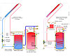
Figure 3.
Sealed Off
Two examples ofclosed-loop solar drainback systems for domestic water heating are shown inFigure 3. Both systems are completely closed from the atmosphere and operate under a slight positive pressure.The system on the left uses a separate solar storage tank with internal copper or stainless steel coil for domestic water preheating. Cold domestic water passes through this coil first, and then on to the conventional tank-type water heater for any necessary temperature boost. The drainback reservoir is at the top of this tank. Auxiliary energy is only added to the conventional water heater when necessary. This allows the solar storage tank to operate at lower temperatures that help boost collector efficiency.
The system on the right uses a separate drainback tank, which can be elevated above the main storage tank, if necessary, to reduce the lift head of the collector circulator. Hot water returning from the collectors passes through this insulated drainback tank, and then flows through the lower coil of the main storage tank. Auxiliary energy is added at the top of the storage tank when necessary.
Pressurized, closed-loop drainback systems have several advantages, including:
Drainback solar subsystems should never have an automatic make-up water assembly. Doing so would eventually cause the air in the subsystem to be replaced with water and, thus, eliminate the required drainback volume. Any minor water losses can be monitored using the sight glass, and manually “made up” by adding water through the lower hose bib valve.
In October, we will get into the specifics of sizing the circulator for drainback systems.

