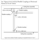
“Figure A.9.3.2.3(2)(a) Flexible
Coupling on Horizontal Portion of Tie-In”
There have been significant changes to NFPA 13, Standard for the Installation of Sprinkler Systems, between the 2002 edition and the 2007 edition. This article will address the major technical changes that are contained within the 2007 edition of NFPA 13 relating to seismic protection of automatic sprinkler systems. This article will not cover each and every change or review the existing requirements that have been contained in previous editions of NFPA 13.
The 2007 edition made specific seismic changes in nine specific areas including flexible sprinkler hose fittings, obstructions to sprinklers caused by seismic bracing or restraint, flexible couplings, seismic separation assemblies, lateral sway brace spacing and loads, horizontal seismic loads, maximum allowable brace loads, maximum allowable fastener loads, and restraint of branch lines.Each of these areas will be discussed in detail with the final text of NFPA 13 included in bold (versus plain) text.
1. Flexible Sprinkler Hose Fittings
While on the surface the new requirements for the use and installation of flexible sprinkler hose fittings does not appear to have an impact on seismic design, the committee provided additional annex material addressing the potential benefit of utilizing flexible sprinkler hose fittings in seismic areas due to their ability in providing the necessary deflection under seismic conditions. Currently, ASCE 7-05, Section 13.5.6.2.2(e) requires that where the suspended ceiling and the sprinkler system are not tied together to respond as an integral unit, either a 2 in. (50 mm) oversized opening be provided to allow for at least 1 in. (25 mm) of free movement in all directions or a swing joint be provided that can accommodate 1 in. (25 mm) of ceiling movement in all horizontal directions. While flexible sprinkler hose fittings are not required to be utilized by NFPA 13, they provide a listed alternative to large oversized openings around sprinkler penetrations in seismic areas. When adding the requirements to NFPA 13, the committee addressed three main areas including listing (9.2.1.3.3.1), ceiling construction and installation (9.2.1.3.3.2) and maximum unsupported length (9.2.1.3.3.3) as shown in NFPA 13 Section 9.2.1.3.3 as follows:9.2.1.3.3* Flexible Sprinkler Hose Fittings.1
A.9.2.1.3.3 Examples of areas of use include clean rooms, suspended ceilings, and exhaust ducts.1
9.2.1.3.3.1 Listed flexible sprinkler hose fittings and its anchoring components, intended for use in installations connecting the sprinkler system piping to sprinklers shall be installed in accordance with the requirements of the listing including any installation instructions. 1
9.2.1.3.3.2 When installed and supported by suspended ceilings, the ceiling shall meet ASTM C635, Standard Specification for the Manufacture, Performance, and Testing of Metal Suspension Systems for Acoustical Tile and lay-In Panel Ceilings and shall be installed in accordance with ASTM C636, Standard Practice for Installation of Metal Ceiling Suspension Systems for Acoustical Tile and lay-In Panels.1
9.2.1.3.3.3* Where flexible sprinkler hose fittings exceed 6 ft (1.83 m) in length and are supported by a suspended ceiling, a hanger(s) attached to the structure shall be required to ensure that the maximum unsupported length does not exceed 6 ft (1.83 m).1
A.9.2.1.3.3.3 The committee evaluation of flexible sprinkler hose fittings supported by suspended ceilings was based on a comparison of the weight of a 6 ft, 1 in. diameter Schedule 40 water-filled unsupported armover weighing approximately 13 lb to the weight of a 6 ft, 1 in. diameter water filled flexible hose fitting weighing approximately 9 lb. The information provided to the committee showed that the maximum load shed to the suspended ceiling by the flexible hose fitting was approximately 6 lb and that a suspended ceiling meeting ASTM C635, Standard Specification for the Manufacture, Performance, and Testing of Metal Suspension Systems of Acoustical Tile and lay-In Panel Ceilings, and installed in accordance with ASTM C636, Standard Practice for Installation of Metal Ceiling Suspension Systems for Acoustical Tile and lay-In Panels, can substantially support that load. In addition, the supporting material showed that the flexible hose connection can be attached to the suspended ceilings because it allows the necessary deflections under seismic conditions.1
2. Obstructions to Sprinklers
Where bracing and restraint is added to mains and now in some cases to branch lines, there is a possibility that if either the brace or the restraint is located too close to the sprinkler it will obstruct the discharge of the sprinkler and, therefore, the obstruction rules of Chapter 8 apply in these cases as follows.9.3.1.4 Obstructions to Sprinklers. Braces and restraints shall not obstruct sprinklers and shall comply with the obstruction rules of Chapter 8.1
3. Flexible Couplings
Two specific areas requiring flexible couplings were added or modified to address flexible couplings for floor tie-ins and for drops to hose lines, rack sprinklers, and mezzanines. Section 9.3.2.3(2) was modified to address the location of flexible couplings where a floor tie-in does not incorporate a riser and where the tie-in is horizontal only. Figure A.9.3.2.3(2)(a) illustrates this arrangement.9.3.2.3 Systems having more flexible couplings than required by this section shall be provided with additional sway bracing as required in 9.3.5.3.7. The flexible couplings shall be installed as follows:1
(2) Within 12 in. (305 mm) above and within 24 in. (610 mm) below the floor in multistory buildings. When the flexible coupling below the floor is above the tie-in main to the main supplying that floor, a flexible coupling shall be provided as follows:1
(a)*On the horizontal portion within 24 in. (610 mm) of the tie-in where the tie-in is horizontal or,1
(b)*On the vertical portion of the tie-in where the tie-in incorporates a riser.1
See “Figure A.9.3.2.3(2)(a) Flexible Coupling on Horizontal Portion of Tie-In” below.
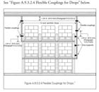
9.3.2.4* Flexible Couplings for drops. Flexible couplings for drops to hose lines, rack sprinklers, and mezzanines shall be installed regardless of pipe sizes as follows:1
- (1) Within 24 in. (610 mm) of the top of the drop1
(2) Within 24 in. (610 mm) above the uppermost drop support attachment, where drop supports are provided to the structure, rack, or mezzanine1
(3) Within 24 in. (610 mm) above the bottom of the drop where no additional drop support is provided1
See “Figure A.9.3.2.4 Flexible Couplings for Drops” below.
4. Seismic Separation Assemblies
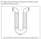
For the 2007 edition the committee has expanded its requirements and allowances for seismic separation assemblies. Figure A.9.3.3(b) was added to address an example of the new allowance for the use of flexible piping in lieu of a series of pipe, fittings and couplings. The required (9.3.3.2) movement must accommodate closing of the separation and opening of the separation to twice its normal size with movement in the other two dimensions equal to the separation distance. Section 9.3.3.3 and 9.3.3.4 address the need for a four-way seismic brace within 6 ft (1.8 m) on both sides of the seismic separation assembly and the requirement that no bracing be attached to the seismic separation assembly.9.3.3* Seismic Separation Assembly.1
See “Figure A.9.3.3(b) Seismic Separation Assembly Incorporating Flexible Piping” below.
9.3.3.1 An approved seismic separation assembly shall be installed where sprinkler piping, regardless of size, crosses building seismic separation joints above ground level.1
9.3.3.2 Seismic separation assemblies shall consist of flexible fittings or flexible piping so as to allow movement sufficient to accommodate closing of the separation, opening of the separation to twice its normal size, and movement relative to the separation in the other two dimensions in an amount equal to the separation distance.1
9.3.3.3* The seismic separation assembly shall include a four way brace upstream and downstream within 6 ft (1.83 m) of the seismic separation assembly.1
A.9.3.3.3 Each four-way brace should be attached to the building structure on opposite sides of the seismic separation joint.1
9.3.3.4 Bracing shall not be attached to the seismic separation assembly.1
5. Lateral Sway Bracing
The biggest area of change for the 2007 edition involves the spacing criteria of lateral braces. These changes were needed to ensure that NFPA 13 met or exceeded the design requirements of ASCE 7-05,Minimum Design Loads for Buildings and Other Structures. While the requirements of Section 9.3.5.3.1 remained the same, additional annex text was added to clarify the new requirements.9.3.5.3 Lateral Sway Bracing.1
9.3.5.3.1* Lateral sway bracing shall be provided on all feed and cross mains regardless of size and all branch lines and other piping with a diameter of 21/2 in. (65 mm) and larger.1
A.9.3.5.3.1 A brace assembly includes the brace member, the attachment components to pipe and building, and their fasteners. There are primarily two considerations in determining the spacing of lateral earthquake braces in straight runs of pipe: (1) deflection and (2) stress. Both deflection and stress tend to increase with the spacing of the braces. The larger the mid-span deflection, the greater the chance of impact with adjacent structural/nonstructural components. The higher the stress in the pipe, the greater the chance of rupture in the pipe or coupling. Braces are spaced to limit the stresses in the pipe and fittings to the levels permitted in modern building codes, with an upper limit of 40 ft. The braces also serve to control deflection of the pipe under earthquake loads. In the longitudinal direction, there is no deflection consideration, but the pipe must transfer the load to the longitudinal braces without inducing large axial stresses in the pipe and the couplings.1
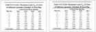
9.3.5.3.2* Lateral sway bracing shall be spaced in accordance with Table 9.3.5.3.2(a) or Table 9.3.5.3.2(b), and spacing shall not exceed a maximum interval of 40 ft (12.2 m) on center. The maximum permissible load in the zone of influence of a sway brace shall not exceed the values given in Table 9.3.5.3.2(a) or Table 9.3.5.3.2(b).1
A.9.3.5.3.2 The sway braces spacing in Table 9.3.5.3.2(a) and Table 9.3.5.3.2(b) were developed to allow designers to continue to use familiar concepts, such as zone of influence, to lay out and proportion braces while ensuring compatibility with modern seismic requirements. The spacing of braces was determined using the provisions of ASCE 7, Minimum Design Loads for Buildings and Other Structures, assuming steel pipe with threaded or grooved connections. The tabulated values are based on conservative simplifying assumptions. A detailed engineering analysis, taking into account the properties of the specific system, might provide greater spacing. However, in order to control deflections, in no case should the lateral sway brace spacing exceed 40 ft (12.2 m).1
Historically, NFPA 13 has permitted the last lateral brace to be a maximum of 20 ft from the end of the pipe. However, having a large section of pipe extended beyond the last lateral brace creates a significant stress and failure point for the sprinkler system. In order to reduce the stress and deflections to allowable limits, the maximum distance was reduced to 6 ft.
9.3.5.3.4 The distance between the last brace and the end of the pipe shall not exceed 6 ft (1.8 m).1
[Part 2 of this article will run in a future issue ofpme.]