Packaged domestic water booster systems have evolved to the point where if you can dream it, it can be built. Each project is unique, and each owner/operator has his/her own set of needs and capabilities. That withstanding, a domestic water booster system still has one purpose--to maintain a constant water pressure throughout a building and to its fixtures.
In looking at designing, sizing and selecting a packaged booster system, it's important to understand some common industry terms that will help you understand the packaged booster system and how it is designed as a whole.
A packaged domestic water booster system refers to the pumps, motors, valves, headers and electric controls all being factory assembled, piped and wired on a common steel skid. System pressure is the pressure required at the discharge connection at the booster system to operate all the fixtures within the building. Working pressure is the sum of maximum possible suction pressure and the pump shutoff pressure. You must compare the working pressure to the pressure rating of the pump castings, fittings and hydro-pneumatic tank to ensure their pressure ratings are sufficient. System capacity refers to the total flow requirement of the building in gallons per minute (gpm).
Now that we have a better understanding of the characteristics of a packaged booster system, let's look at the two basic types of domestic water booster systems, constant speed and variable speed.
Constant Speed Booster Systems
In a constant speed booster system, the pump motor operates at its rated speed regardless of the flow conditions. The pressure that is being produced by the pump is determined by the amount of water that is being demanded by the building.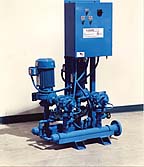
How Does It Work?
A constant speed booster system travels along the pump curve from maximum flow to shutoff. As the water demand in the building diminishes, the pressure output of the pump generally rises. This variation in pressure produced by the pump makes pressure reducing valves (PRV) necessary for each pump. The PRV enables the system to operate at variable flows while maintaining a constant pressure. This will also be true if the city suction pressure fluctuates.The most common way to cycle domestic water booster systems is through monitoring the system pressure with a pressure switch located on the system's discharge header.
A booster system should not run continuously, particularly if there is no demand for water. Once the pump has satisfied the system pressure, a minimum run timer is actuated, and the pump will run for a preset time. The run cycle is usually five to seven minutes. If the system pressure is not satisfied at any point during the cycle, the timer is reset and the cycle restarts. If one pump cannot satisfy the system pressure within a preset time delay (usually five seconds), a second pump is called to run. A hydro-pneumatic tank is always present on a constant speed system to prevent the pumps from short-cycling.
How Many Pumps Should Be Used?
All domestic water booster systems used in commercial buildings should use multiple pumps. This applies for both constant and variable speed systems. Water usage studies have shown that in typical applications, water demand is less than 20% of our calculated system capacity for more than 70% of the time. To better match actual conditions, each pump in a duplex system can be sized for 50% of the total flow. If redundancy is required, a system with each pump sized for 65% of the flow is adequate. Any way you split the pump loads, it will save on horsepower.
The line between duplex and triplex is usually drawn at 300 gpm. On triplex systems, a jockey pump can be selected at 20% of the total flow, with the other two pumps each sized for 50% of the total flow. This allows for a jockey, which will run most of the time, and 100% backup. You could also select three pumps at 50% of the total flow. This allows 100% backup if any one of the pumps were to fail. It also allows for even wear across the pumps.
How Does the Hydro-Pneumatic Tank Work?
A constant speed system requires a hydro-pneumatic tank to keep the line pressurized once the system is shutoff. When possible, the hydro-pneumatic tank is mounted adjacent to the system. This will allow for the tank to receive full, unregulated pressure by making its connection to the system prior to the pressure-regulating valve on each pump. While the system is experiencing low flow, the pump's discharge pressure is rising. The PRV is holding a constant pressure, so any additional water pressure is diverted to the tank. The larger the difference between system pressure and final tank pressure (pump shutoff plus suction pressure), the greater the water storage in the tank bladder.
The following is the formula to calculate storage capacity. It is also known as Boyle's Law (P1V1 = P2V2). For this example let's assume: Suction pressure = 30 psi, Pump shutoff = 45 psi, System pressure = 60 psi, and a 132-gallon tank. (Note: The usable storage in the tank is reduced 7% by the tank bladder.)
Mp = Max pressure (pump shutoff + suction pressure)
V = Volume of compressed air
S = System pressure
C = Capacity of tank less 7%
MpV = SC
75V = 60 x (132 x .93)
V = 98 gallons of compressed air
Total water storage capacity = 24 gallons
When the pump has completed its cycle and has satisfied the system pressure for the duration of the run timer, it will shut down. Water will then be drawn from the tank until pressure drops below the pressure switch set point. This 24 gallons of water from the example determines how long the booster system will rest before turning on a pump again.
What If the Tank Has to Be Mounted in the Penthouse?
When the working pressure is greater than the rating of the tank, the tank must be located at a higher point in the building, usually in the penthouse. The system pressure remaining at the top of the building will fill the tank. In other words, system pressure minus static head minus friction equals the pressure remaining at the top of the building. Since we are using controlled pressure (after the PRV), we cannot expect any additional pressure to be available at the tank connection, so we simply pre-charge the tank for 5-10 psi less than the pressure calculated at the tank connection. This does not allow for the tank to be filled with much water, but prevents the pumps from short-cycling. This is why it is preferable to locate the tank adjacent to the system.Variable Speed Booster Systems
In a variable speed booster system, a variable frequency drive adjusts the speed of the pump motor to operate on an "as needed" basis. As the building demands less water, the motors are able to slow down.How Does It Work?
Once again, we are cycling the booster system by monitoring system pressure. The variable frequency drives (VFDs) will speed up or slow down in reaction to changes in our system pressure via a pressure transducer. Since the VFD is adjusting the pump's output pressure to satisfy a fixed system pressure, in theory the PRVs are no longer needed.
A hydro-pneumatic tank is not required for a variable speed system. A pressure transducer will monitor system pressure to detect if flow exists. If no flow exists, the system would eventually fall into "sleep" mode if properly designed.
Well, How Slow Can You Go?
The pressure-speed relationship is based on the Pump Affinity Laws. The Affinity Law that relates Speed and Pressure states that the pressure varies by the square of the speed. In the example here, "H" represents Pressure (Head) and "N" represents Speed (rpm).H1/H2= (N1/N2)2
Example: In a high-rise building 100 feet tall, water has to be boosted 100 feet. If a 3,500 rpm motor is slowed to 2,900 rpm, solve the equation for H2.
100/H2 = (3,500/2,900)2
H2 = 69 Feet
When the motor speed was slowed to 2,900 rpm, the pump was only capable of boosting the water to 69 feet. In addition, The Pump Affinity Laws state that the gpm capabilities vary directly with motor speed. The speed was reduced by 17%; therefore, the gpm capability would also be reduced by 17%.
When Should Variable Speed Be Used?
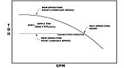
When selecting a pump, plot the duty point on the curve. Then draw a straight line horizontally to the beginning of the grid. This represents variable speed operation. At random, choose points along that horizontal line and compare them to where you would be operating on the pump curve in a constant speed system (Figure 1). Then use the following equation to calculate Brake Horse Power for both the constant speed and variable speed points:(GPM x TDH)/(3,960 x Pump Efficiency) = BHP
When comparing variable speed to constant speed, there's not much of a difference in savings on the 3, 5, 7.5 and 10 horsepower. When using steep head curves, the difference is greater than when using flat head curves. However, when suction pressure varies on a daily basis as little as 15 psi, variable speed is validated. Remember, booster pumps are sized based on absolute minimum suction pressure. If, in fact, the city pressure is actually 20 psi higher than we used in our sizing, a variable speed system would recognize the difference and operate at a lower speed. Some other benefits of variable speed systems are their quiet operation and decreased wear on the pumps and motors. The slower a motor operates and the higher the pump efficiency, the longer the motor bearings and pump seal will last. This is due to decreased radial and axial shaft thrust. Again, a hydro-pneumatic tank is not required on variable speed systems. This will save space in the mechanical room and gives the owner/operator one less thing to maintain.
For buildings over 50 stories, tank fill systems should be considered. These systems use variable speed pumps in stages, taking suction from a tank. The pumps on the bottom floor would serve a number of floors and fill a tank on a higher floor. Another booster would take suction from that tank to serve a number of floors above that, and so on. Variable speed is the best way to accomplish this system, because the water usage in each booster zone will be minimal for most of the day.
What Happens If a Drive Fails?
If you do choose variable speed, constant speed bypass should be considered. Constant speed bypass allows the pumps to run at constant speed if a variable speed drive has failed or malfunctioned. When constant speed bypass is used, the system must have PRVs, which are set 5 psi higher than the system pressure so they don't interfere with normal variable speed operation. If a variable speed drive fails and the system does not have constant speed bypass, the pump would not operate. This is to save the building from high-pressure output of non-regulated pump pressure.Summary
For systems under 15 hp, constant speed systems are a good choice. They are easily serviced and adjusted, and there are fewer electronics.When space and noise are important factors, or where suction pressure varies, variable speed systems should be used.
If you have calculated everything accurately and selected the best pump for the job, the system will operate as you design it. Whether it is constant or variable speed, your client will have many years of trouble free service.
