Issue: 1/03
Many articles have been written over the last decade about various hydronic system designs. The focus has almost always been on the load and delivery design characteristics. Very little attention has been given to the source of energy...the boiler. This article will focus on protecting non-condensing boilers from premature failure caused by low temperature return water.
Non-condensing boilers represent the majority of boilers currently in use and installed today. If misapplied, non-condensing boilers can fail prematurely from thermal shock and long-term boiler condensate production. In fact, even misapplied condensing boilers can be damaged by thermal shock conditions. This article proposes to examine the factors that lead to premature failure, along with providing some practical solutions for both existing and new installations.

Why Now?
There appears to be a dichotomy in the industry. Some say that there isn't a problem in the industry; it's just the boiler manufacturers making cheaper boilers. Others say that it's about time someone finally addresses this problem. Who's right? The evidence points to the latter.Over the last decade, there have been a number of factors, both governmental and private, that have created a marketplace for smarter designs and improved seasonal efficiencies. As a result, the latest boiler sizing practice has produced less backup and redundancy in the boiler room. The boilers have become smaller as a result. In addition, lower mass boiler designs have germinated because of governmental pressure on increasing efficiency. The impact of this downsizing and lower mass has been a higher sensitivity to the temperature and volume of return water back to the boiler. Many premature boiler failures can be traced to these uncontrolled conditions. Other factors that have created this surge in boiler failures are:
- An increasing application of low temperature systems such as snow melting and radiant flooring.
- Poor system integration and control.
- Outdoor reset and warm weather shutdown capabilities.
- Misunderstanding of the protection value of primary/secondary systems.
- Conversion of steam systems to hot water, while retaining the original oversized distribution systems.
- Conversion of gravity flow systems to pumped systems, while retaining the original oversized distribution systems.
Thermal Shock
Thermal shock is the term that is used to describe the rapid reduction of water temperature within a boiler. The severity of the thermal shock is based on two primary factors: the magnitude of the shock (change in temperature) and the frequency (how often it occurs). The greater the magnitude and frequency, the sooner the failure. Thermal shock subjects the boiler to the repeated expansion and contraction of the pressure vessel wall material. All materials will fail if subjected to a sufficient number of cycles and magnitude of thermal shock. This type of failure is otherwise known as cyclical fatigue. The repeated bending of a paperclip is another example of cyclical fatigue. Bending the paperclip simulates the thermal shock that a boiler experiences. Bending the paperclip to extremes will cause a failure quickly. Bending the paperclip to smaller deflections but in a quick repetitive motion will also cause the paperclip to fail quickly.
Another example helps to explain the potential for premature boiler failure by examining a typical fall day in New England. The building used in this example is a brick 50-unit apartment building that uses two boilers with a total capacity of 150% of full load. Domestic hot water is produced with the use of indirect water heaters through a domestic priority controller, meaning that the demand for domestic hot water production has a higher priority than the heating system. The heating zones created no demand since it was a bright sunny afternoon with outdoor temperatures in the mid-70s. The temperature of the water in the distribution piping cooled down to ambient conditions. Between 5 and 6 p.m., a number of demands for domestic hot water resulted in the repetitive operation of the boilers. Boilers that are used for indirect water heating are typically set at a minimum of 180 degrees F. After a domestic hot water cycle, one of the large zones containing 73 degrees F water energized, allowing cold water to return to the boiler. Subsequently, the bulk boiler water temperature decreased from 180 degrees F to 73 degrees F in less than one minute. Actually, this occurred several times during the early evening since the heating cycles were disrupted to allow for priority domestic hot water generation. This type of scenario is common in today's marketplace. Repeating this type of thermal shock may cause premature boiler failure.

Designing the Solution
Designers are often challenged with determining "how much is enough" when designing hydronic systems for new and retrofit applications. Designers often balance the concepts they have used before with new approaches they may have recently learned. What every designer wants, if able to win the opportunity, is an installation that satisfies the customer's need...forever. No designer wants to look over his or her shoulder in the meantime, questioning the integrity of the system.The use of primary/secondary piping has been promoted for a number of years. The benefit of a primary/secondary piping scheme is to hydraulically decouple the main supply loop from individual heating zones through the use of closely spaced tees. In other words, the system pump does not influence the flow through zones. The variants of parallel piping schemes make it difficult for the designer to control the flow of heat delivery, or living space comfort. The demands on comfort today force the designer to pay close attention to system flows. Unfortunately, this greater attention to comfort has overshadowed the factors influencing boiler longevity.
Many solutions have been offered over the years. Some have said that primary/secondary piping alone protects boilers; however, under close examination, one can see that a reduction of risk is possible but not prevention. Primary/secondary piping schemes blend flows from various zones into a common primary loop. The boiler(s) is connected to this same loop, injecting heat into the loop while the primary loop water returns directly into the boiler (Figure 1).
The boiler in a primary/secondary arrangement is experiencing a constant flow. This is an improvement over a typical parallel piping system that utilizes the system pump as the boiler pump too. However, the fallacy about the boiler protection value of a primary/secondary arrangement can be seen when examining the temperature of the return water into the boiler. Nothing prevents ambient water conditions from entering the boiler. During the spring and fall, multiple zone activation during a load change can still return water as cold as the ambient temperature in the living space.

One Solution
How does one prevent the return of cold water into the boiler? There have been articles written in the past that have addressed boiler protection for low temperature radiant systems. These articles have addressed both thermal shock and sustained flue gas condensation in non-condensing boilers. The same concepts apply for boilers in conventional higher temperature designs. By utilizing this same technology, boilers can be impervious to low temperature return conditions. The concept is based on a positive means for preventing the return of low temperature water into the boiler. If the "boiler envelope" is extended to include boiler protection, the designer can be confident that he will specify a design that will not be influenced by low temperature return water.There are four basic methods for protecting the boiler from low temperature return water:
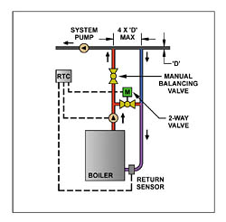
- Two-way valve injection
- Three-way valve diverting or mixing
- Four-way valve mixing
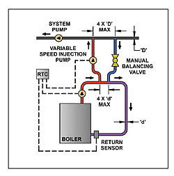
- Variable speed injection pump
Each of these approaches, when included within the boiler envelope, allows the designer to easily incorporate this protection scheme in both retrofit and new installations. All four protection schemes rely on a sensor, located on the return inlet to the boiler, as well as a boiler circulator to maintain a constant flow through the boiler (Figures 2-5). A common control target is to prevent the return of water lower than 135 degrees F. This prevents the boiler from operating in a condensing mode, as well as minimizing the amount of shock or temperature change magnitude.
The Impact to the System
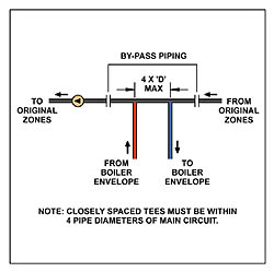
When selecting the approach that works best for any particular application, consider the impact to the entire system. The decision making process is more difficult with a retrofit application because of limitations regarding the existing piping scheme. Consider treating the boiler envelope as the heat source that injects heat into the building system. The less need for change in the building system, the simpler the design and operation. This can't be avoided with a parallel piping system since it will be necessary to convert it to a primary/secondary arrangement. However, this can easily be converted by adding a bypass when installing the two closely spaced tees (Figure 6).The control logic for all four options is the same. The flow of supply water from the boiler is allowed to flow into the system, provided the return sensor is above the setpoint, in this case 135 degrees F. The flow into the system from the boiler envelope will increase as the valve opens or the pump speed increases, provided the return sensor is satisfied. If the temperature in the return line decreases, the valve will continue to close to maintain a safe condition. In the case of the variable speed injection pump, the pump speed will decrease to maintain the same safe condition. Although this is a rather simple explanation, the control algorithms can be very sophisticated, as satisfactory performance is expected.
The two-way valve can be an effective approach; however, the additional need for a two-way manual balancing valve in the boiler loop adds an element of uncertainty. The designer becomes responsible for setting the balancing valve to assure proper flow characteristics. Flow balancing for any given system is often overlooked at best.
The three-way valve approach brings a simple, time-proven approach to boiler protection. The three-way valve, boiler circulator and return sensor, when part of the boiler envelope, create an effective protection solution without impacting the operation of the building's primary loop. The three-way valve offers an economical and effective approach as a diverting or mixing valve.
The four-way valve is also an effective approach to boiler protection when it is part of the same boiler envelope described previously. Some have claimed that the boiler circulator can be avoided with a four-way valve because of the induced flow from the building system pump. If so, the additional cost of the four-way valve can be defrayed by the absence of the boiler circulator pump. However, the flow through the boiler counts on the induced "ghost" flow, potentially subjecting the boiler to flow rates below a safe minimum value. When in doubt, a boiler circulator is always recommended. In addition, a manual valve is added to the return loop to create a pressure drop for assuring proper flow into the primary loop.
Some have used variable speed injection pumps with success. The variable speed injection pump transfers the heat from the boiler envelope into the building's primary loop. The boiler circulator is still required to maintain the desired flow through the boiler. It is necessary to analyze the difference between the initial and operating costs when evaluating the valve and pump approaches. The amount of useful flow turndown with a variable speed pump will generally be less than the turndown ratio of a valve, especially when variable speed drives (VFDs) are used.
While the selection of an appropriate boiler protection method is the responsibility of the designer, it makes sense to consult the boiler manufacturer for a recommendation of components that will work best with the company's products.
Summary
The advancement of hydronic systems over the last few years has created a need to examine the conditions that have resulted in premature boiler failures. Some of the factors that can lead to an increase in boiler failures are:
- Reduction of boiler capacity redundancy.
- Lower mass in boiler material of construction.
- Lower mass in boiler water volume.
- Conversion of steam systems to hot water.
- Conversion of gravity flow systems to pumped systems.
- An increasing application of low temperature systems.
- Poor system integration and control.
- Outdoor reset and warm weather shutdown capabilities.
- Misunderstanding of the protection value of primary/secondary systems.
Provided the heating system is designed as a primary/secondary loop, boilers can be protected from low temperature return water by using a number of effective techniques. Each of these techniques essentially isolates the boiler loop from the primary loop using a mixing device, allowing the injection of heat into the system.
Although the selection of the correct approach is ultimately in the hands of the designer, the boiler manufacturer can play an important role by specifying the approach that works best with its product. The shift in attention to boiler protection can improve the image of the hydronics industry, and it is the last challenge in this new frontier.
