
- Most have expansive, bare slab-on-grade concrete floors that offer minimal upward resistance to heat flow and relatively simple tubing installation.
- Most need a rugged heat-delivery system not susceptible to damage from vehicle traffic and associated vehicle and equipment maintenance activities.
- Many require interior air temperatures in the mid 60°F range, which often allows for reduced water supply temperatures to floor circuits.
- Most have high ceilings that encourage undesirable air temperature stratification if convective heat delivery is used. Radiant floor heating prevents this stratification and can even eliminate the need for "paddle fans"
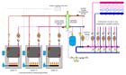 Figure 2
Multiple-Boiler Systems
The days when a single, large, knock-down cast iron boiler was a "given"In systems where the distribution system operates at lower water temperatures, modulating/condensing boilers (typically referred to as "mod/cons" Figure 3When a system of conventional boilers is used, heat can be transported to the manifold stations at higher supply temperature. This allows the high temperature difference between boiler supply water and return flow to be exploited. Distribution flow rates to a remote manifold station can be reduced in inverse proportion to this temperature difference. The savings in distribution piping installation cost can be significant. This concept, known as a minitube system, is shown in Figure 4 on page 77.
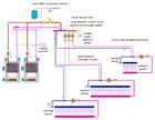 Figure 4
Another factor affecting boiler selection is venting. All modulating/condensing boilers use sealed combustion and sidewall venting, typically through PVC pipe. This can substantially reduce installation cost relative to chimney venting, which is still the preferred option for conventional boilers.
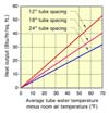 Figure 5
Wide Tube Spacing
Large garage facilities are not places where people walk around barefooted. This allows for greater variation in floor surface temperature, with little concern about complaints from occupants. Tube spacing of 18 and even 24 inches can be used to reduce installation cost.The graph in Figure 5 shows the expected upward heat output from a 6-inch-thick heated concrete slab with 5/8" PEX tubing placed at 12-, 18- and 24-inch spacing. This graph is based on finite element analysis. Upward heat output is shown as a function of the temperature difference between the average circuit water temperature and the room air temperature.
Assume, for example, that a building required an upward heat flux of 30 Btu/hr/ft at design load conditions. The interior of the building is to be maintained at 65°F. If 12-inch tube spacing is used, the required average circuit water temperature is 65 + 40 = 105°F. At 18-inch spacing, this temperature increases to about 65 + 52 = 117°F. At 24-inch spacing, the average circuit water temperature required is 65 + 65 =130°F.
So which spacing/water temperature should you select? It depends.
If a conventional boiler is used, the higher water temperature can be easily produced via a mixing device with the boiler operating perhaps 10-20°F above this temperature. If a minitube distribution system is used, the size of that mixing device-as well as the size of the distribution piping-depends on the difference between boiler supply temperature and the return temperature from the distribution system. The greater the difference between these temperatures, the lower the flow in the distribution system.
If a condensing boiler is used, it will experience a loss of efficiency when operating at elevated temperatures.
The only way to make an informed decision is to compare the cost savings associated with wider tube spacing against the higher operating cost associated with somewhat reduced boiler efficiency.
Personally, I like to specify 12-inch tube spacing in the vicinity of overhead doors, loading docks and perimeter areas subject to higher loading due to their proximity to outdoor conditions. I also use 12-inch spacing in any office areas along the exposed perimeter of the building. Wider tube spacing is then used on interior areas. We have done several large garage facilities using 18-inch interior tube spacing and found the results very satisfactory.
Continuous Circulation
Garage facilities often contain areas of concentrated heat loss, such as just inside larger overhead doors, at loading docks and the floor areas under vehicles shedding snow. Such areas can dissipate heat significantly faster than interior slab areas.An ideal way to minimize cold floors in these areas is by continuous circulation through floor circuits. This allows heat stored within the interior slab areas to be shuttled to localized "heat sinks,"
Anti-Antifreeze?
In years past, I typically specified antifreeze within the entire hydronic system at large garage facilities. This protected the system from freezing should a heavy ice storm take out utility power for several days. This protection came at the expense of several negatives associated with the use of glycol-based antifreeze (reduced thermal capacitance, increased head loss, propensity to weep through threaded joints, added installation cost and long-term fluid maintenance).Today, many commercial garages have a standby generator that can be operational in a very short time (a few hours at most). This allows for continuous circulation, which, depending on the load, can prevent freezing for up to several days, even if the boiler plant is non-operational.
Another factor affecting the choice of straight water or an antifreeze solution is the availability of repair parts. In systems using multiple boilers and smaller "residential size"
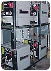 Figure 6. Rack-mounted modulating/condensing boilers. (Photo courtesy of Heat Transfer Products.)
Smaller Footprint
Engineers often complain that the size of the mechanical room provided by the architect is too small to install the necessary equipment. In such situations, the architect is trying to conserve "finished" Figure 7
Life Beyond 20
It's customary to design hydronic distribution circuits for a temperature drop of 20°F. Although I'm not sure of the origin of this custom, I can assure you that the vast majority of hydronic distribution systems-systems that provide excellent comfort-don't operate at this condition. Some operate at lower temperature drop because the installed circulator is capable of flow rates higher than calculated during system design. Some also operate at higher temperature drops because of the flow resistance of the tubing circuits, and other hardware has been underestimated.In residential floor heating systems, I prefer to limit circuit temperature drops to 15°F to reduce variations in floor surface temperature across the room. Such variations can be detected with bare feet, and may lead to complaints even when sufficient heat is being delivered to maintain the room's thermostat setpoint.
However, in large garage facilities, it's possible to design with circuit temperature drops of 20-25°F. As with wider tube spacing, this compromise is very unlikely to cause complaints because garage floors don't need to be "barefoot friendly."
Something to Watch Out For
Many large garage facilities are constructed of steel frames engineered for structural efficiency. The idea is to get the greatest enclosed square footage for the least cost. Unfortunately, the insulation systems used in these structures are often an afterthought rather than a tightly integrated part of building design.Be mindful of the fact that a heated floor will evaporate any floor moisture that doesn't run down the drain.
Large amounts of snow melting from vehicles will definitely push up interior humidity levels-in some cases high enough to cause condensation on framing and fasteners where insulation is either not present, has been compacted or where no sealed vapor barrier exists. I have seen this on several such structures. In many cases, the floor heating system gets the blame, even though the problem is lack of insulation, vapor barrier detailing or poor building ventilation given the internal moisture load.
If you're involved in the floor heating system for a building like this, be sure to have a look at the insulation and vapor barrier detailing, and bring this possibility to the attention of the building designers and/or owner before they have water dripping from the ceiling. Proper moisture control through vapor barrier detailing, dehumidification or ventilation is the way to prevent the problem.
Summary
The concepts we've discussed hold the potential to reduce the cost of floor heating systems in large garage facilities relative to current practice. Some, such as periodic flow reversal, reduced flow rates and high circuit temperature drops, are synergistic. As always, be sure to run the numbers based on life-cycle owning and operating costs when integrating these concepts into your future system designs.
