
Discharge Head
The required discharge head, whether expressed in feet of head (ft.) or pounds per square inch (psi), is the pressure that is required to produce the sum of:
- The required residual pressure at the highest, most remote fire department valve outlet at the required flow rate.
- The frictional losses of fittings, valves and lengths of piping in the flow path, adding the friction of subsequent flowing standpipes from the most remote outlet back to the source fire pump.
- The static elevation pressure of the most remote outlet's location (2.31 ft. = 0.434 psi).
The required residual pressure varies with the codes in question. For example, the requirements are 25 psi in New York, 65 psi in Chicago and 100 psi for the International Building Code and International Fire Code. The 100 psi requirement appears in NFPA 14, the Standpipe Installation Standard.
The piping design layout influences the frictional losses. The Building Code may dictate requirements for the piping layout, especially as the building's overall height increases, resulting in the need for multiple zones.
For example:
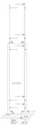
- Chicago allows a single standpipe zone height of up to 275 feet (see Figure 1). Above that height, separate additional zones of a maximum 20 stories each are required. The additional zone must be supplied by a minimum of two express risers per zone.
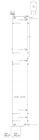
- New York requires a roof tank on buildings higher than 300 feet and an additional manually controlled fire pump (see Figure 2 on page 80). Upper levels of the standpipe system must be supplied from the roof tank. The low zone of the system must have the pressure reduced to 160 psi maximum.
- NFPA 14 requires 4" minimum diameter standpipes and 6" minimum diameter combined sprinkler/standpipes be connected by a common bulk main from the fire pump at the lowest level (see Figure 3 on page 82). If a roof tank is a part of the design, the standpipes may be connected at the top level, with check valves to prevent circulation. Pressure regulating valves are required to reduce pressures if the pressure is greater than 175 psi.
Design Points on the Fire Pump Curve
The estimated discharge pressure for the system is established at the pump's discharge flange. The estimated gallons per minute flow rate required for the system's supply is determined using the required pressure. The duty point or "Primary Rating Point"
Tips for Reducing Shut-Off Pressures in System Designs
If the maximum churn pressure of the system exceeds the listing pressure of the sprinklers installed in the system, the following may reduce the rise to shut-off head pressure:
- 1. Upgrade the sprinklers and piping to a higher listing pressure if only a few floors exceed the maximum.
- Low zone fire pumps should always be provided with a full-size bypass from the suction to the discharge. During maintenance procedures, the lower-floor sprinkler systems may be kept in service utilizing the water supply pressure.
- Make sure that there are no abrupt changes of direction at the suction flanges of either horizontal-split case or vertically mounted horizontal-split case pumps. These changes in direction will cause cavitation in the double suction impellers.
- Where vertically mounted pumps are selected, be sure that space and provisions are provided to lift the motor from the pump frame during maintenance procedures.
- When pumps are required to be connected to a second emergency source of power, make sure the fire pump controllers specified have an integral automatic transfer switch.
- If the emergency source of power is a generator set, specify a "reduce voltage starting type"
SIDEBAR:Why Maximum Pressure Rating is Important
Early sprinkler/standpipe systems had only upright, pendent or horizontal sidewall sprinklers. The piping system was Schedule 40 steel pipe with threaded or flanged 125-pound valves and fittings. These 125-pound fittings were installed in systems that had a maximum pressure of 175 psi. For systems having a pressure in excess of 175 psi, extra heavy 250-pound valves and fittings were installed. Extra heavy fittings were considered acceptable for systems having a maximum pressure of 400 psi.What is often forgotten is that the125-pound and 250-pound designations were a "nominal class rating."
Links
2. Select a fire pump model that has 20% or less rise to shut-off, not 40%.
3. Consult the manufacturer's representative to determine if the model with the lowest rise to shut-off is being specified. Trimming the impellers may reduce the rise to shut-off further. Only certain manufacturers and models may benefit from trimming, with some having a rise to shut-off as low as 5% above the system's required duty point.
4. If two fire pumps are piped in series for the high zone, determine whether the high zone pump can meet the zone requirement by taking suction directly from the residual city water main in parallel. This avoids adding two rise to shut-off pressures to the water supply static pressure.
5. Increase the system pipe sizes to reduce the friction loss in the system.
6. Consult the fire pump controller manufacturer regarding the use of a "variable speed controller"

Tips for System Layout
The layout of a multiple pump system should be provided adequate space for maintenance, with 3 feet of aisle space around all pumps and controllers, and with system control valves. This also provides access to fire department personnel in an emergency.Some suggested tips: