
Primary/secondary (P/S) piping has established itself as the default piping technique for multi-load hydronic systems. It's ability to "keep the peace" among several simultaneously operating circulators is what makes it the preferred choice over other types of distribution systems.
The best-known form of P/S piping arranges the secondary loads in sequence along a common primary loop as shown in Figure 1. Such a configuration is more specifically called a series primary loop.
Each secondary circuit connects to the primary circuit using a pair of closely spaced tees. These tees should be as close together as possible. Install the tees with the indicated minimum lengths of piping both upstream and downstream. These straight sections of pipe reduce turbulence that can interfere with the tees' ability to uncouple the pressure dynamics of one piping circuit from another.
One question that repeatedly comes up in discussions of P/S systems is how to select the primary loop circulator. Here are some myths and facts surrounding this question.
- MYTH 1: The primary loop circulator must be the largest circulator in the system.
- FACT: Although the primary pump may be the largest circulator in the system, it may also be the smallest. Its size is determined by the rate of heat production of the system's heat source, as well as the selected temperature drop of the primary loop at design load conditions.
- MYTH 2: The primary loop circulator must produce a flow rate equal to or greater than the total flow rate of all secondary circuits.
- FACT: This is not true. The total of all secondary circuit flow rates may be several times the flow rate in the primary loop.
- MYTH 3: The primary circulator must be selected so the primary loop will operate with a 20 degrees F temperature drop at design load conditions.
- FACT: Also untrue. The temperature drop of the primary loop may be less than or significantly greater than 20 degrees F. The latter case often holds significant advantages in terms of reducing installation and operating cost.
Every circulator in a primary/secondary system operates as if it were installed in an isolated circuit. The primary circulator does not assist in moving flow through any of the secondary circuits, or vice versa. The function of the primary loop is simply to convey the output of the heat source to the secondary circuit "pick up" points, while operating at or close to a selected temperature drop.
Primary Loop Flow Requirement
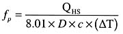
The flow rate necessary to deliver the full output of the heat source at a specific temperature drop can be found using Formula 1.Where:
fp = required flow rate in the primary circuit (gpm)
QHS = heat output rate of heat source (Btu/hr)
deltaT = intended temperature drop of the primary circuit (degrees F)
D = the fluid's density at the average system temperature (lb/ft3)
c = the fluid's specific heat at the average system temperature (Btu/lb/degrees F)
8.01 = a constant
In small to medium size hydronic systems, the product of (8.01 x D x c) can be taken as 490 for water, 479 for 30% glycol, and 450 for 50% glycol.
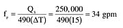
Here's an example: Assume a primary circuit is connected to a boiler having an output of 250,000 Btu/hr. The intended temperature drop of the loop under design load conditions is 15 degrees F. What is the necessary primary loop flow rate? How does the flow rate requirement change if the primary loop is operated with a 30 degrees F temperature drop?

Doubling the intended temperature drop of the loop cuts the required flow rate in half. Not only does this reduce the required pipe size, it also reduces the size of the circulator. The smaller circulator will likely operate on lower wattage, and thus reduce the operating cost of the system. Considering that the primary loop circulator operates whenever any secondary circuit is running, the savings in operating cost can be substantial.
Here's an example: Assume an 80-watt circulator can provide the 16.7 gpm flow in the previous example, but a 200-watt circulator is needed to operate the loop at 33.3 gpm. Also, assume the primary loop circulator operates 3,000 hours per year in an area where the current cost of electricity is $0.12 per kilowatt-hour. What's a conservative estimate for the difference in operating cost over 20 years?
The operating cost of the larger circulator is:
20 year op. cost = (0.200kw)(3000 hr/yr x 20yr)($0.12/kwhr) = $1440
The operating cost of the 80-watt circulator is:
20 year op. cost = (0.80kw)(3000 hr/yr x 20yr)($0.12/kwhr) = $576
The difference in operating cost over 20 years is $864!
Furthermore, this simple calculation does not account for inflation in the purchase cost of electricity, and thus the actual savings is likely to be higher.
Once the primary loop flow rate and pipe size is determined, the designer estimates the head loss of the primary loop based on the piping components it contains. The flow rate and head loss set a target operating point for the primary loop circulator. A circulator with a pump curve passing through or just above this point should be selected. Ideally, the operating point should fall in the middle third of the pump curve to maintain reasonably high pump efficiency. If the operating point is characterized by high flow and low head, consider the use of two parallel circulators rather than a single circulator.
Notice that a primary loop circulator can be selected without reference to the secondary circuits. Likewise, each secondary circulator can be selected based solely on the flow and head loss requirements of the secondary circuit it serves.

Think Deep DeltaT
It's apparent that selecting "deep" temperature drops for the primary loop can lower both installation and operating cost. This is a situation to be "exploited" in systems having both higher temperature and lower temperature loads. A good example is a system that supplied both fin-tube convectors and low temperature radiant floor heating, as shown in Figure 1.The higher temperature secondary circuits should always be connected near the beginning of the primary loop, where water temperatures are highest. The lower temperature loads are often supplied through mixing devices such as a motorized four-way valve or variable speed injection pump. These subsystems should be connected near the end of the primary loop, where water temperatures are lower.
Be sure the mixing device can deliver the necessary rate of heat transfer when operating at the "hot" water inlet temperature available near the end of the primary loop.
If a conventional boiler is used as the heat source, also verify that the return water temperature is high enough to prevent sustained flue gas condensation. A good target is no lower than 130 degrees F under design load conditions.
The drop in water temperature as the primary loop flow passes an operating secondary circuit can be calculated using Formula 2.
Where:
deltaTp = the temperature drop in primary loop as it passes an operating secondary circuit (degrees F)
Qs = rate of heat output to the secondary circuit (Btu/hr)
fp = flow rate in the primary circuit (gpm)
D = the fluid's density at the average system temperature (lb/ft3)
c = the fluid's specific heat at the average system temperature (Btu/lb/degrees F)
8.01 = a constant
For systems where the average temperature of the primary loop is 140 degrees F to 150 degrees F, the product of (8.01 x D x c) can be taken as 490 for water, 479 for 30% glycol, or 450 for 50% glycol.
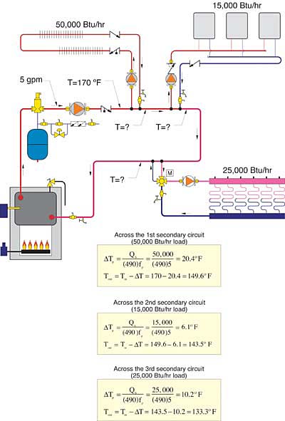
The 133.3 degrees F water returning to the boiler is hot enough to prevent sustained flue gas condensation in a conventional boiler. If a condensing boiler is used, the inlet temperature to the boiler should be as low as possible to promote condensing mode operation. In the latter case, the limiting factor will be the required supply temperature of the last secondary circuit connected to the primary loop.
Parallel Primary Loops
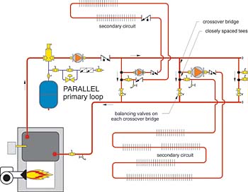
When several secondary circuits have approximately the same water temperature requirement, they are best supplied from a parallel primary loop, as shown in Figure 3.In a parallel primary loop, each secondary circuit is supplied from a pair of closely spaced tees that connect to a crossover bridge. These crossover bridges assure the same water temperature is delivered to each secondary circuit. The closely spaced tees ensure there will be no interference between simultaneously operating circulators.
Each crossover bridge should be equipped with a balancing valve so flow rates can be proportioned to the load served by each bridge.
Selecting a circulator for a parallel primary loop is very similar to the procedure used for a series primary loop. The total loop flow rate can again be calculated using Formula 1 along with a selected temperature drop. The flow rate through each crossover bridge can then be proportioned to the load served by that bridge relative to the total system load. Pipe sizes can then be selected for each crossover bridge as well as the common piping.
The operating point for the primary loop circulator can be estimated by calculating the head loss around the path of greatest flow resistance and combining this with the total primary loop flow rate. This operating point can then be plotted on the pump curves of candidate circulators. A circulator with a pump curve passing through or just above this point can then be selected.
As with series primary loops, the higher the temperature drop across the crossover bridges, the lower the flow requirement. It should also be noted that different crossover bridges could operate with different temperature drops when necessary.
Summary
Because the primary loop in a P/S system always operates as if it were a standalone circuit, selecting a circulator for it is really no different than selecting a circulator for any other hydronic circuit. The steps are:
- 1. Determine the rate of heat delivery available from the heat source.
2. Pick a target temperature drop for the primary loop.
3. Calculate the primary loop flow rate needed based on 1 and 2.
4. Estimate the head loss of the primary loop at this flow rate to get the operating point.
5. Select a circulator with a pump curve passing through or just above this operating point.
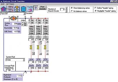
1 The Hydronic Circuit Simulator is one of several design tools available in the Hydronics Design Studio. This software will be released in May 2003. Watch PME for an announcement.
