Providing equipment selection and pipe sizes that deliver adequate water flow to plumbing fixtures and equipment in tall buildings is an important design task of the plumbing design professional.
Providing equipment selection and pipe sizes that deliver adequate domestic water flow within useable pressure ranges to plumbing fixtures and equipment in tall buildings is an important design task of the plumbing design professional.
The necessary design tasks include:
-
Determining the "code-allowed maximum" delivery pressure to fixtures and the "minimum useable" delivery pressures of the "exact fixtures" to be included in the project. Using the code minimum delivery pressure for design purposes and installing fixtures with higher than the code minimum requirements will result in poor or unacceptable performance. The most demanding pressure requirements are likely to be shower valves, which vary widely by manufacturer.
-
Determining the "maximum probable water flow demand" of fixture groups using the Fixture Unit method and Hunter's Curve, and estimating the "minimum probable water flow demand" using evaluation and experienced judgment of the fixture groups, building type and projected use.
-
Determining the system pipe sizes and friction loss of supply piping to fixture groups at "maximum probable flow rate."
-
Determining locations of pressure reducing valve (PRV) equipment, considering adequate space for servicing, sounds produced by normal operational noises and safety in the event of valve malfunction.
-
Determining the available inlet pressure at PRV equipment and the desired outlet pressure to plumbing fixture groups based on relative locations of stations and fixtures within the building height.
Basic Valves
Smoothly operating PRV stations that instantaneously reduce a higher inlet pressure to a steady lower downstream pressure, regardless of changing flow rate and/or varying inlet pressures, are accomplished using two types of pressure reducing valves.
-
Direct-acting, spring-loaded valves are used for low flow rates.
-
Pilot-operated, diaphragm-actuated pressure-reducing valves are used for higher flow rates.
The primary differences between these two types of valves are the style of operation, pressure losses through the valves and available sizes.
The direct-acting, spring-loaded valve uses the tension of a spring to close the valve disc against the seat, thus providing a pressure loss or reduction as water flows through the valve. Simple in its operation, the direct-acting valve has a "continuously increasing pressure loss" as water flow increases through the valve, compressing the spring. The pressure difference between the minimum and maximum water flow rates can be as high as 50 psi, making them perform poorly at high flow rates.
The diaphragm-actuated, pilot-operated valve, in contrast, can maintain a steady downstream pressure with a constant, minimal pressure loss through the valve-normally 3-5 psi across the entire flow range of the valve. However, its limitation is that at minimum and intermittent flow rates near the shut-off point of the valve, the pilot system may "hunt" for the correct seat position, producing noise and chatter, and causing "wire drawing" of the seating surfaces.
Wire drawing occurs when the valve disc and seat position operate for extended periods of time close to the shut-off point of the valve, and the water flow erodes or scores a pathway in the seating material that remains when the valve closes tight to the shut-off position. This allows small flows and pressure "creep" from the inlet to the outlet side of the valve at the closed position. Pressure creep into the distribution system is relieved with the operation of plumbing fixtures; however, in systems where fixtures may be lightly used over a weekend, as in a commercial building, the pressure creep may exceed the temperature and pressure relief valve settings on local water heaters throughout the building. The resulting unattended discharge of water from T&P relief valves may cause extensive water damage and bring litigation against the designer's firm.
Wire drawing of valve seat materials can be mitigated by the correct sizing of the valve (smaller is better here, as a smaller valve opens more widely) or the specification of stainless steel seats that resist the scoring action of the water at low flows.
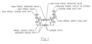
Figure 1
Parallel and Staged Series Arrangements
The limitations of each valve type can be successfully overcome by their use together, in parallel, with each valve overcoming the limitations of the other. The direct-acting valve is operational for low flows, and the diaphragm valve is operational for high flows above a preset maximum pressure drop of the direct-acting valve. Selecting valve sizes that allow the direct-acting valve to provide for 1/4 to 1/3 of the maximum probable flow demand, and the diaphragm valve to provide for the remaining maximum probable demand, will result in a smoothly operating pressure reduction across the full range of required flow. Arrangements may have the direct-acting valve included in the pilot piping of the diaphragm valve body to reduce the space required for overall installation, or it may be piped separately from the main valve (Figure 1).
Staged series arrangements of PRVs become necessary when the amount of pressure reduction required exceeds the ability of single valves in parallel to provide smooth pressure reduction without "cavitation." When the required pressure reduction from very high inlet pressures to normal code maximum delivery pressure causes a single valve to operate near its shut-off position to achieve the desired results, cavitation will occur as a result of the high velocity and turbulence created.
Cavitation is a hydraulic dynamic caused by excessive velocity and turbulence that momentarily pulls water apart into its gas constituents of hydrogen and oxygen, then collapsing back into liquid water. The result causes deterioration of internal valve parts and premature failure.
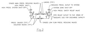
Figure 2
Arranging two PRVs in series to accomplish high pressure reduction allows the valves to reduce pressure in a staged manner, with each valve accomplishing a portion of the required pressure reduction, and it allows each valve to be significantly more into its full open position, avoiding cavitation and turbulence. The PRV station at the bottom of a very tall building, where flows vary widely and pressure reduction is significant, may need to be arranged in both series and parallel valve arrangements to smoothly accomplish its task (Figure 2).
Valve Size Selection, Typical Station Trim and Safety Components
To summarize, for smooth operation, widely ranging flows need parallel valves for transitions between high and low flows, and high pressure reduction requires multiple valves in series. Now we can begin to utilize the information developed by the previously mentioned "necessary design tasks" to configure and specify equipment. Friction loss of supply piping to fixture groups and pressure drop through the PRV at maximum probable flow must be included in the outlet pressure figure.
Pressure-reducing valve sizes should be selected with minimum-maximum flow data and the required inlet-outlet pressures from the sizing data of a single valve manufacturer, utilizing cavitation charts to determine the need of "valves in series" to avoid cavitation. If the manufacturer's data does not include cavitation charts, consult your local representative or factory directly.
Contacting the specific manufacturer to confirm and advise on your selections prior to bid issue is a wise step. This gives them the opportunity to confirm your intended design and suggest additional options, such as "opening and/or closing speed controls in the piloting piping" to smooth valve operation, or the arrangement of pilot piping to provide a "high-pressure safety shut-down" if valve outlet pressures exceed intended design due to a valve diaphragm failure.
Valve sizes and type selection with detailed piping arrangement of the stations should be shown in the contract documents, and a Pressure Reducing Valve Schedule should be completed to indicate the location, valve sizes, minimum-maximum flow and inlet-outlet pressure requirements at each station.
The information shown will be based on a specific manufacturer and will allow other bidding manufacturers to confirm the arrangement and advise on the selection of their valves that provide for the elimination of cavitation and show a smooth transition between valves and flows, assuring proper operation regardless of which manufacturer supplies the equipment to the project.
A typical high-rise zone of predominately flush valve plumbing fixtures will likely result in a supply pipe size of 4" diameter, a low flow valve size of 3/4" or 1" diameter, and a high flow valve size not greater than 1-1/4" to 1-1/2" in diameter.
Show and specify the following trim components:
-
System shut-off valves on the supply inlet and outlet to fixture groups. When maintenance of valves is desired without PRV interruption, additional shut-off valves should be provided on the inlet and outlet of each PRV to isolate them from the system separately.
-
Threaded unions between PRVs.
-
Pressure gauges on the inlet and outlet of the station, and between staged valves in series.
-
A pressure relief valve sized to relieve the maximum inlet supply pressure of the station to an acceptable open site drain, in the event of PRV diaphragm failure and the resulting discharge of water from the safety valve.
-
A bypass globe valve around PRVs, sized no larger than the high flow PRV size (optional).
-
Supply line and pilot line strainers, based on water quality and suspended particulate.
Thoughts on Maintenance and Safety Trim
Water quality has the most direct effect on the need and frequency of maintenance of PRV stations.
Planned maintenance at intervals that "prevent the failure in service of PRVs" is the best approach. If the main valve fails in service, the small valve will never cover the load at maximum probable demand.
Normal points of failure are clogging of the pilot trim, resulting in erratic operation or the failure of a diaphragm, in which case the PRV makes no pressure reduction until repaired. If the unreduced inlet pressure to the PRV is greater than the listed normal operation pressure of pipe and fittings supplying fixture groups, specify a pressure relief valve or a safety shut-off valve on the station outlet.
A safety shut-off valve is the basic valve with pilot modifications that will sense a rise in pressure from a failing PRV and close tightly, preventing high pressure from entering a supply zone downstream and causing fitting failures and water damage.
The usefulness of a manual globe bypass valve (intended to be adjusted manually by a technician to keep a system in operation while repairing a PRV) is questionable. Wire drawing is again the concern, and the finished repair may be made worthless. Wire drawing can occur with a large diameter globe valve operating near its seat when it is used during repair. When the service contractor places the PRV back into operation, he or she may fail to notice the small pressure creep that results from the wire-drawn seat on the bypass globe valve. This increased pressure may be slow to build and could possibly be relieved with the normal fixture use until the system is unused at night or over weekends. The excessive pressure builds through the wire-drawn seat of the bypass globe, around the just serviced PRV station, and into the supply system, resulting in T&P relief valves opening and damage to piping, fittings and valves having a lower pressure rating.
An improperly designed PRV station can have very detrimental results, such as excessive noise in the building, premature failure of the valve/pipe/fittings and possible water damage. Be sure to spend the necessary amount of time in the design, specification and detailing of PRV stations.
Self-Contained and Remote Pilot Arrangements
The discussion of pilot trim has so far been of the internal or self-contained type, meaning that the pilot locations are on the inlet and outlet of the specific PRV. The plumbing design professional should understand that many options of hydraulic control are available, utilizing different piloting modifications with the same basic valve. Designers will benefit greatly from a manufacturer's sales presentation, as the number and details of options are best explored in a format where questions can be addressed for greater understanding of the full design potential of their products.
Example
The use of a remote pilot location rather than internal piloting at the basic valve has allowed the design of centralized domestic hot water systems with centralized recirculating returns from separate supply zones of different pressures to be realized. Hot water generated at the top of a tall building has the design advantages of dramatically less static head pressure on heating equipment, shorter flues with gas- or oil-fired equipment, and less overall equipment space required, versus individual water heaters located within each supply zone. Although hot water pressure reduction to fixture groups can be accomplished in an identical manner to the supply of cold water, combining recirculated returns from supply zones with different pressures into a centralized return system has eluded designers until recent years.
The Problem
Previous unsuccessful attempts utilized simple check valves at the point where recirculating zones of different pressures were combined into a central system. The problem is that the zone of highest pressure held the clappers of other lower pressures zones closed, or partially closed; thus only the zone with the highest pressure received adequate recirculation flow.
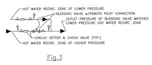
Figure 3
A Solution
Using remote piloting, a basic valve installed in a recirculation line of a higher pressure zone will sense the lower pressure from a separate zone and reduce its higher inlet pressure to match, at its outlet, the lower pressure of a different supply zone, regardless of changes in flow or pressure of either system. The pressure difference between zones is justified in a dynamic manner, allowing them to combine under all operational circumstances (Figure 3).
After all zones are combined into a single recirculation line and pumped back to the water heating equipment, the same valve/remote pilot arrangement can be used to reduce the recirculation line pressure to that of the lower pressure of the domestic cold supply to the water heaters, completing the centralization of the domestic hot water recirculation system.

