Figure 1.
For years I’ve described radiant panel heating in North America as “the tail wagging the hydronics dog.” During the last 25 years, radiant panel heating was largely responsible for leading the North American hydronics market out of the doldrums of the 1970s to 25+% per year market growth at the close of the 1990s. Many hydronic heating pros that got into the market during this time cut their teeth designing and installing radiant panel heating systems.
Given this coalescence of interest in radiant panel heating, one might wonder if there’s any future for other types of hydronic heat emitters. I firmly believe the answer is yes! This month we’ll look at one alternative that I think is one of the most “underutilized” heat emitter options in the North American market – the panel radiator.
The goal of this article is not to convince you to “switch” from radiant panels to panel radiators, but rather to expand your awareness of the possibilities of designing with panel radiators and compare their attributes to the current standard bearer of heat emitters – radiant floor heating.
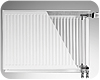
Figure 2.
What is a Panel Radiator?
That’s a common response when the term “panel radiator” is mentioned to a client as a possible heat emitter option for their project. At present, panel radiators are not well known outside of the hydronic trade in North America. This is in sharp contrast to a relatively high consumer awareness of radiant floor heating.All panel radiators release a combination of radiant and convective heat into a room as hot water flows through them. Beyond this fundamental function is a virtually unlimited range of forms, sizes, colors, and artistic themes.
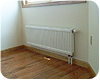
Let’s start with a basic “utility grade” panel radiator, such as shown (installed) inFigure 1, and as a cutaway inFigure 2.
The front of the panel radiator is called the “water plate.” It consists of two formed steel sheets welded together at their perimeter and across the face. The upper and lower portions of the water plate act as headers. Several vertical flow channels run between these headers.
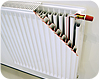
Figure 3.
Many panel radiators of this type have supply and return piping connections at the bottom, and a preinstalled flow control valve in the upper right corner (as seen in Figures 1 and 2). Water flows into the bottom left connection, up a riser and through the flow control valve, and then out across the water plate. After flowing downward through the water channels, flow exits through the bottom right connection.
The internal volume of the water plate is very low relative to a typical cast-iron radiator of similar frontal area. For example: A 24-inch-high by 48-inch-wide panel radiator with a single water plate only holds about 0.7 gallons of water. The empty weight of this panel is about 75 pounds.
These characteristics produce a heat emitter with very low thermal mass relative to its heat output capability. This allows for fast response, both warming up and cooling off. A panel radiator can quickly begin radiating heat to a cool space and quickly stop releasing heat should internal gains occur.
This is in marked contrast to the response characteristics of many radiant floor panels, especially those with tubing embedded in poured slabs. These slow-response characteristics often rule out radiant floor heating in situations where loads change rapidly due to internal heat gain.
To increase heat output without changing face dimensions, manufacturers join two or sometimes three water plate/fin assemblies together into a single assembly as shown inFigure 3.
Panel radiators with two or three water plates have a higher percentage of convective heat output than do single water plate panels operated under the same conditions. They also project farther out from the wall as shown inFigure 4.
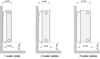
Figure 4. Panel radiators with 1-3 water plates.
Form and Function
When was the last time you looked at a radiator as the embodiment of artistic expression? Although some older cast-iron radiators have their share of ruffles and ridges, few match the imagination shown in some modern panel radiator offerings such as the unit shown inFigure 5.As with most artistic creations, cost is not the primary consideration leading to the purchase of such radiators. They aren’t cheap, but they are functional heat emitters, and can be mixed into a system with other types of panels.

Figure 5. Courtesy of Vasco.
Beyond 20ºF
Another advantage panel radiators hold over radiant floor heating is the ability to operate at relatively low flow rates and higher temperature drops. Many panel radiator systems in Europe are designed for 20ºC (36ºF) temperature drops at design conditions. This is approximately double the design temperature drop used in most radiant floor panel systems.Radiant floor panels need lower circuit temperature drops to reduce variations in floor surface temperature to enhance the desired “barefoot friendly” feel. Some suppliers even suggest limiting design temperature drops in radiant floor panels to 10ºF. Although this does reduce variations in floor surface temperature, it also necessitates larger circulators and substantially higher circulator power consumption.
Designing a panel radiator system for higher temperature drop has several benefits:
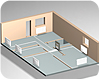
Figure 6. Courtesy of DiaNorm.
Distribution Decisions
Panel radiators can be used with many piping layouts, including series loops, diverter tee loops, two-pipe parallel direct return and two-pipe parallel reverse return.As with other hydronic heat emitters, series or diverter tee layouts require the size of the radiator be adjusted to compensate for decreasing water temperature in the downstream direction. Although possible, these approaches do not offer the two key benefits of a parallel distribution system, namely:
Perhaps the most versatile distribution system for panel radiators is the “home run” system using PEX or PEX-AL-PEX tubing to and from each panel radiator as shown in Figure 6. All the supply and return runs come from a manifold station – just like in a radiant panel system.
Home run distribution systems provide the same water temperature to each panel, and thus simplify sizing. They also allow each circuit to be balanced for proper flow. The latter can be done using valves built into the manifold station, or with integral balancing valves built into certain types of panel radiators, as shown in Figure 7.
Room-by-room comfort control is easily achieved using a home run distribution system in combination with panel radiators equipped with non-electric thermostatic radiator valves. For radiators such as shown in Figure 7, the thermostatic operator just screws onto the radiator’s flow control valve as shown in Figure 8. This operator uses the expansion and contraction of a wax-filled actuator to move the stem of the radiator valve as needed to maintain the room setpoint temperature.
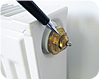
Figure 7.
Putting It All Together
Suppose you need a system that provides room-by-room comfort control, utilizes a high efficiency modulating/condensing boiler, is simple to install, and economical to operate. Consider the layout shown in Figure 9.This design provides room-by-room comfort control using a home-run distribution system. Each radiator is equipped with a non-electric thermostatic radiator valve. A pressure-regulated circulator automatically adjusts its speed to maintain the required differential pressure as the radiator valves modulate between open and closed.
The high-mass mod/con boiler maintains the proper supply water temperature to the distribution system based on outdoor reset control. Its high thermal mass and low head loss eliminate the need for a separate boiler circulator. For the features offered, it doesn’t get much simpler than this.

Figure 8.
Some More Comparisons:

Figure 9.
They're Not Mutually Exclusive
There are applications where it makes sense to combine the attributes of radiant floor panels and panel radiators. An example would be use of radiant floor heating in a basement slab in combination with panel radiators on the main floor. The schematic inFigure 10shows how such a system can be piped.Water temperature control to the panel radiators is handled by the outdoor reset controller within the mod/con boiler. A manually-set (non-motorized/non-thermostatic) mixing valve is used to provide proportional reset control to the lower temperature radiant floor circuits in the basement slab.
The heat output of each panel radiator is controlled by a non-electric thermostatic operator mounted to the integral valve on each radiator.
When domestic water heating is required, the boiler goes to a higher setpoint temperature and the circulator connecting the boiler to the space heating system is turned off. This treats domestic water heating as the priority load. Once the domestic water heating cycle is completed, space heating can resume.
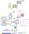
Figure 10.
Summary
Both radiant panels and panel radiators have their place in the hydronics universe. Both have optimal application scenarios in which the other simply isn’t an option. For example, using panel radiators to heat a 10,000-sq.-ft. vehicle maintenance garage doesn’t make sense.Likewise, installing radiant floor heating in an existing building with inaccessible floor structure and expensive surface finishes is virtually out of the question. Seasoned designers recognize these situations and apply each technology to maximize performance and benefits to the customer.
