Issue: 9/02
Twenty-five years ago, just about every residential and light commercial hydronic heating system used a single boiler as its heat source. Most of these boilers had a "tankless coil" for producing domestic hot water. Most served two to four zones of high temperature heat emitters, such as fin-tube convectors or cast-iron radiators. Fuel was relatively cheap, and so was skilled labor. Energy conservation was hardly a priority. Oversizing was common and not viewed as a problem in the American tradition of "Bigger is Better."
Times have changed. Today, many residential and light commercial hydronic systems serve multiple and diverse loads, such as space heating, domestic water heating, pool heating and snowmelting. At times, the instantaneous demand for heat can be very large, while at other times, a mere trickle of heat is needed by one small heating zone.
One approach is to install a single boiler capable of supplying the peak demand of all loads should they ever operate simultaneously. Another is to install a separate "dedicated" boiler for each of the major loads. While both approaches have been used on many systems, neither represents the best modern hydronics technology has to offer.
Divide and Conquer
In multiple boiler systems, the total output is divided up among two or more boilers, referred to as "stages." Only the boilers that are needed to closely match the heating load at any given time are fired. This allows boilers that are being fired to operate for longer periods. Their efficiency increases, much like the average miles per gallon of a car increases when most of the driving is highway mileage rather than "stop-and-go" driving.Because they can be controlled in stages, multiple boiler systems can adapt to the wide range of heat output requirements often demanded by modern, extensively zoned systems. They do so while maintaining significantly higher seasonal efficiency than a single larger boiler.
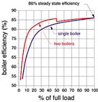
The curves in Figure 1 show why this happens. The blue curve shows how the efficiency of a typical gas-fired atmospheric boiler decreases from a maximum steady state value of about 86% as the load decreases. At load factors less than 30%, boiler efficiency drops rapidly as standby heat losses during long off-periods claim more and more of the heat.
When the load is divided equally among two boilers, the efficiency curve, shown in red in Figure 1, begins to flatten out. At 50% load, one of the two boilers is running at or very close to 86% steady state efficiency. The other boiler is completely off. When the system requires 20% of full load, the one boiler that's firing is operating at about 40% of its rated output, and thus is higher on its efficiency curve.
As the load is divided up among even more boilers, an efficiency curve that is based only on combustion efficiency would continue to flatten and shift toward the steady state value. However, another factor is at work that is counterproductive to this trend. That factor is heat loss from the boiler jacket, which becomes a larger percentage of boiler output as the rated capacity of the boiler decreases.
As the load is divided among more and more boilers, jacket heat loss increases, and eventually offsets any incremental gains in efficiency due to additional stages. Based on this, and other practicalities such as the cost of isolation and safety hardware on each boiler, it seldom makes sense to use more than four stages in any residential or light commercial applications.
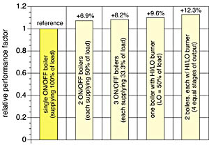
The bar graph in Figure 2 shows projected savings of some common multiple boiler configurations relative to a single on/off boiler sized to match the design heating load.
But Wait--There's More
In addition to high seasonal efficiency, multiple boiler systems provide other benefits such as:
- Partial heat delivery if one boiler is down for servicing. This is a major consideration in locations where service is more than a few hours away, or where extreme temperatures can quickly freeze non-operational systems.
- The ability to meet high peak demands. As the opulence and number of bathrooms used in many custom homes increases, so does peak demand for domestic hot water. A multiple boiler system can help provide this peak demand without sacrificing efficiency under much lower space heating loads.
- The potential to eliminate several other dedicated heat sources distributed throughout the building, as well as their associated fuel supplies, electrical hook-ups and exhaust systems. Systems that use separate boilers for each of several loads cannot "share" boiler output among the loads. A boiler that's dedicated to snowmelting is of no assistance during a high demand for domestic hot water. A boiler that only heats the pool is of no use should the space-heating boiler be down for service. The idea is to make all the heat output capacity accessible to all the loads.
- Smaller/lighter boilers are far easier to install than a single larger unit, especially on retrofit jobs. Repair parts are also more readily available for smaller boilers. Anybody who's ever removed an old cast iron boiler using the sledge hammer method knows what I mean.
Piping Possibilities
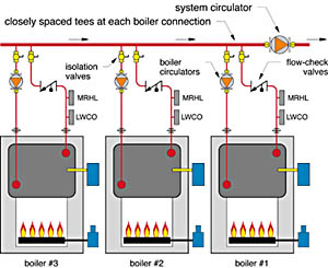
To achieve the highest possible efficiency, it's imperative that multiple boilers are piped and controlled so heated water is not circulated through unfired boilers. Doing so simply uses the inactive boilers as heat emitters.One piping option that meets this requirement is shown in Figure 3. Each boiler is connected to the main system piping using a pair of closely spaced tees (or T-drilled connections). Because of the tiny pressure drop in the main pipe between these connections, there is very little motivation for water to flow down through a boiler unless that boiler's circulator is operating. A flow-check or spring-load check valve prevents any water flow through the boiler until it is fired and its circulator is operating.
One disadvantage of this series primary/secondary approach is that it creates higher entering water temperatures in the downstream boiler(s) when more than one boiler is firing. The higher water temperatures increase stack temperature and jacket heat loss in the downstream boilers, which slightly degrades their efficiency.
Another factor to consider with the piping shown in Figure 3 is that two tees are required to connect each boiler into the main. If the size of the main is large, these tees and their installation labor can get expensive.
Notice that a separate low water cut-off (LWCO) and manually reset high limit (MRHL) control are shown on each boiler. This is usually required by mechanical code when each boiler can be isolated by valves from the system piping (which is certainly desirable if servicing is required).
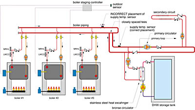
An alternative piping alternative is shown in Figure 4. In this approach, each boiler is piped in parallel with the others. All boilers connect to a common set of headers that in turn connect to the main system piping using a closely spaced set of tees (e.g. primary/secondary piping). This prevents the system pump from interfering with flow through the boilers. Again, each boiler's circulator only operates when the boiler is fired. This piping method provides the lowest water temperature to each boiler, which improves efficiency, albeit at the expense of slightly more involved piping.
With either piping method, the boiler circulator must provide the head loss of the boiler and a small amount of connecting piping. The boiler circulator does not assist with flow through the main distribution system.
While selecting the boiler circulator, designers should verify the acceptable temperature rise across the boilers they plan to use. For example, most cast iron sectional boilers are capable of operating with temperature rises of at least 40 degrees F. Recognizing this allows the boiler flow rate to be reduced 50% relative to simply assuming a 20 degrees F temperature rise. In many systems, small hydronic zone circulators are more than capable of handling the boiler flow requirement. Using an oversized circulator increases both installation and operating cost. Over the life of the system, the extra electricity used by the oversized circulator may cost several times more than the circulator itself.
Holding the Reins
Modern microprocessor-based controls for multiple boiler systems often perform several functions. For starters, they automatically calculate the proper supply water temperature to the system. If the demand is for space heating, the controller typically determines its target temperature using outdoor reset logic. If the demand comes from domestic water heating, or other loads that use a heat exchanger, the target temperature is usually fixed at some relatively high value (to provide good heat transfer across the heat exchanger). In either case, the controller determines how many boiler stages need to be fired based on PID (Proportional-Integral-Derivative) control logic.Multiple boiler controllers can also be configured to automatically rotate the firing order of the boilers to equalize their accumulated run time. In most situations, this is preferred over a fixed firing order, so all the boilers can be serviced and ultimately replaced with the same accumulated running time.
If the system uses boilers with two-stage (LO/HI) burners, the controller can (and must) be configured to fire the LO stage of a given boiler followed by the HI stage of the same boiler, rather than firing another boiler.
It is crucial to locate the supply temperature sensor for the boiler-staging controller where there is constant flow whenever a load is active. Usually, this is downstream of the closely spaced tees that connect the boiler piping to the system's primary loop, as shown in Figure 4.
A common mistake is to locate the supply temperature sensor on the boiler manifold piping, as shown in Figure 4. The boiler circulators are usually wired so they operate only when their boiler is firing (to provide the necessary isolation of unfired boilers). When the misplaced sensor tells the controller it has reached the desired target temperature, all boilers and their circulators are turned off. The misplaced sensor is now sitting on a pipe full of hot water that is not flowing. Furthermore, the sensor and adjacent piping is usually wrapped in insulation to prevent the sensor reading from being affected by surround air temperature. These circumstances can keep the sensor warm and the boiler controller satisfied (e.g. not firing any boilers) for quite a while. Meanwhile, the primary loop temperature is dropping because heat is being extracted by one or more loads. Unfortunately, flow in the primary loop simply does a u-turn at the closely spaced tees connecting to the boiler piping because there is no flow in the latter. The net result is that residual boiler heat is trapped, even though the primary loop desperately needs it. The staging controller will only fire the boiler when the temperature at the misplaced sensor eventually drops several degrees. Avoid leaving those Btus stranded by placing the supply temperature sensor in the primary loop, as shown in Figure 4.
Leader of the Pack
Although most multiple boiler systems use two or more identical boilers, this is not always necessary. When the load is space heating, a clever alternative is to use a condensing boiler as the "fixed lead," and pair it up with one or more conventional boilers for use when water temperature requirements are higher. The fixed lead condensing boiler is always the first boiler fired by the controller.During mild weather, when the water temperature required by the heat emitters is low, the condensing boiler can supply the load at very high (95+%) efficiency. As the load increases, the water temperature supplied to the distribution system must also increase. As this occurs, the efficiency of the condensing boiler drops, but still remains at or slightly above that of a conventional (non-condensing) boiler. The increasing load is now handled by the conventional boilers operating in the 84-87% efficiency range. At design load conditions, all boilers in the system operate in this efficiency range.
This approach takes full advantage of a condensing boiler when system temperatures are low. It also reduces installation cost by using less expensive conventional boilers when they would be comparable in performance to condensing boilers operating in a non-condensing mode. Modern boiler staging controllers can be configured to make one boiler the fixed lead, while at the same time rotating the firing order of the remaining boilers.
Full Afterburner
Multiple boiler systems are exceptionally well suited to systems that combine space heating with high but intermittent demands for domestic hot water.Consider a situation where the hot water demand is 15 gallons per minute heated from 50 to 120 degrees F. This works out to a heating rate of 525,000 Btu/hr! A 120-gallon tank filled with 140-degree water can supply this load for about nine minutes. After that, it all comes down to raw boiler power.
A multiple boiler system in this situation would go into what I call "full afterburner mode" as soon as it receives a setpoint demand from the DHW tank thermostat. All boiler stages come on in short order as the controller targets a 200 degrees F supply temperature to the DHW heat exchanger. Priority control could be used to temporarily turn off all other loads, so all heat production goes to the DHW load.
For peak performance, the heat exchanger used in the domestic water heating subsystem must be able to "sink" the full heat output of the multiple boiler system into the hot water storage tank. Not all indirect water heaters have the heat exchanger capacity necessary to make this happen. Check out the heat exchanger ratings of any indirect water heater that you plan to use with a multiple boiler system. If necessary, use an external flatplate heat exchanger to ensure there are not "bottlenecks" to heat transfer between the boilers and the tank. This approach is shown in Figure 4.
The use of multiple boiler systems in residential and light commercial buildings will continue to grow as more designers recognize the benefits they offer. Keep the benefits and design details we've discussed here in mind when that next "ideal" multiple boiler application crosses your desk.


