One benefit of hydronic heating is the relative ease of dividing the distribution system into several independently controlled zones. The goal is control--being able to send heat precisely when and where it's needed. Electrically operated zone valves are commonly used to determine which circuits are active at any given time.
Although distribution systems zoned with valves have a well-established track record, they also have the potential to interact with the system's circulator, causing undesirable side effects. The greater the number of zones, and the more powerful the circulator, the greater the likelihood of problems.
The proper use of differential pressure bypass valves (DPBVs) can prevent such problems. This article describes how DPBVs intercede between the zoned distribution system and circulator so the system can provide the quiet and reliable performance expected.
Flatter Is Better
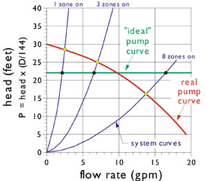
In an ideal hydronic system, the differential pressure between the supply and return side of a given zone circuit would remain constant, regardless of what zone circuits are operating. The circulator would simply provide more or less flow as additional zone circuits open up or close down. To do this, the circulator's pump curve would have to be flat, as shown with the green line in Figure 1.Although some pump curves are flatter (by design) than others, no fixed speed centrifugal pump can operate with a perfectly flat pump curve over its full range of application. As flow through the circulator decreases there will always be an increase in the head energy (foot-pounds/pound) transferred to the fluid. The evidence is an increase in the pressure differential across the circulator.
When zoning is controlled by valves, the flow resistance of the distribution system (as a whole) changes each time a valve opens or closes. At any given time, this resistance determines a unique system curve, a graph of which shows the head loss of the distribution system, in its present operating state, as a function of flow rate.
The intersection of the system curve and the circulator's pump curve is called the operating point. As zone circuits close off, the system curve gets progressively steeper, and the operating point slides upward and to the left along the pump curve. The zone circuits that remain on feel increased differential pressure.
There are a number of undesirable consequences of this higher pressure differential. One is an increase in flow rate in the active zone circuits that can lead to "velocity noise." Besides the obvious acoustical annoyance, high flow velocities can cause erosion of valve seats and other piping components.
Another repercussion of unregulated differential pressure is partial opening of zone valves that are supposed to be off. This leakage allows heated water to migrate into zone circuits that are supposed to be off.
Still another possible problem is inadequate flow through low mass heat sources under low load conditions. Although this can be corrected in other ways, such as making the heat source a secondary circuit in a primary/secondary system, it's much less likely to need correction in systems using a properly set DPBV. That's because the flow through the bypass valve can be rerouted back through the heat source rather than into the distribution system.
The bottom line: The increase in differential pressure across the circulator caused by closed zone valves needs to be limited. When a fixed speed circulator is used, a DPBV provides a reliable means of doing so.
Turning the knob adjusts the spring tension holding the plug against the valve seat. The pressure where the plug just starts to lift away from the seat is called the "threshold" differential pressure. Most DPBVs have a calibrated scale for setting the desired threshold differential pressure. When the pressure differential across the valve is less than this threshold, no flow passes through. The valve is essentially "invisible" to the rest of the system from a fluid dynamics standpoint.
Above the threshold setting, the valve is designed to maintain a relatively constant differential pressure as flow through it increases. Still, like any piping component, friction losses do increase with increasing flow.
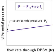
The flow versus pressure drop of a DPBV can be reasonably approximated by the model shown in Figure 3. The vertical intercept of the line is its current threshold differential pressure setting. The slight slope represents the increase in pressure differential due to friction head loss. The slope can be estimated from data provided by the manufacturer. The shallower the slope, the better the valve represents an ideal constant differential pressure device.
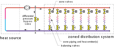
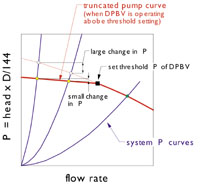
When a DPBV is installed as shown in Figure 2, the pump curve is partially truncated, like in Figure 4. The extent of the truncation depends on the threshold setting of the valve. At differential pressure below the threshold setting, the pump's differential pressure curve is unchanged by the presence of the valve.
Notice the very slight increases in differential pressure when the system is operating above the threshold setting of the DPBV. Compare this to the changes in differential pressure that would occur if no DPBV were present (e.g., where the steeper system curves cross the upper portion of the pump curve).
Setting and Sizing
The following procedure can be used to determine the threshold pressure setting of the DPBV, as well as the maximum flow rate through the DPBV if all zones are closed simultaneously. This setting procedure allows the DPBV to remain "invisible" to the system at design load conditions (when all zone circuits are assumed active), yet come on line quickly as the zones circuits begin to close.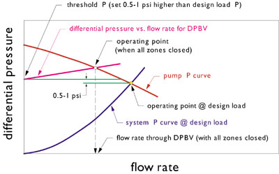
delta = H x D divided by 144
where:
delta = pressure differential (psi)
H = head at pump curve/system curve intersection (feet)
D = density of fluid being circulated (lb/cubic foot)
Step 2: Set the threshold differential pressure of the valve about 0.5 to 1 psi higher than the value determined in Step 1. This allows the DPBV to remain fully closed at design load conditions so all pump flow is directed into the distribution system for maximum heat transfer.
Owing to their European origin, many DPBV valves are calibrated in bars or KPa rather than psi. Use the following conversion factor to convert to psi.
1 psi = 6.895 KPa = 0.068 bar
Step 3: Determine the flow rate through the DPBV when all zones are off. Do this by plotting the differential pressure versus flow rate relationship of the DPBV on the pump's differential pressure curve, and reading the flow rate where the curves intersect (see Figure 5).
Step 4: Select a DPBV from manufacturer's literature that's rated to carry the flow determined in Step 3.
As a practical matter, most residential and small commercial systems can work with either 3/4" or 1" size DPBVs. Larger systems may require 1.25" size valves.
This sizing/setting procedure is conservative in the sense that the DPBV will begin to open at a relatively high percentage of system load. If the designer's objective is solely to prevent flow noise, the valve's threshold pressure could likely be set higher. In some systems, the DPBV is set "in situ" by slowly opening the valve from its fully closed position under a minimal loading condition until excessive flow noise goes away. Such a procedure is acceptable in smaller systems, but doesn't provide the range of quasi-constant differential pressure operation.
Small systems with four or less zones and a circulator no larger than 1/25 horsepower can, in most cases, get along without a DPBV. However, as soon as the system moves beyond this somewhat subjective threshold, a DPBV should be used. When properly selected and set, it serves an important role in helping zoned hydronic systems deliver the quiet performance their owners expect.
