
Remember the days when "hot water heating" in a home or light commercial building usually meant three or four zones of baseboard piped from a single boiler? Space heating was always considered the main load, with domestic water heating via a tankless coil as perhaps the sole ancillary load.
Times have changed. Today, "residential" hydronic systems are often more sophisticated than those used in large commercial buildings. In addition to multiple methods of delivering space heating, such systems routinely provide domestic hot water, snow-melting, intermittent garage heating, and perhaps they even warm the pool in the backyard. What other method of heat delivery can lay claim to such capabilities?
This article examines the building blocks of a modern multi-load hydronic heating system. We'll look at ways to configure the heat source, pipe the system and even select control strategies that allow all the loads to peacefully coexist and deliver the comfort hydronic heating has long been famous for.

One Heating Plant Does It All
The concept underlying the design of many modern hydronic heating systems is: One heating plant supplying many loads.Indeed, no other gas- or oil-fired heat source can be configured to deliver heat to virtually all the heating loads in a house or commercial building. A single heat plant eliminates the need for multiple appliances, each with their own fuel supply, ventilation, exhaust, electrical, space and maintenance requirements. Supplying all loads from a single heat plant increases the duty cycle of that plant, thereby improving fuel efficiency relative to several individually fired appliances.
The heat plant in most modern multi-load hydronic systems is one or more gas- or oil-fired boiler(s). High temperature water (180 degrees to 200 degrees F) is available for loads such as fin-tube convectors and domestic water heating. Medium and low temperature water for other loads is produced using several mixing devices (discussed later).
In some systems, a single boiler can supply all the loads. For larger capacity systems (which today include many single-family residences), a multiple boiler system provides the ideal solution. Such a system can be controlled in stages, allowing it to adapt to a wide range of heat output requirements and retain higher operating efficiency than a single large unit. This ability is especially appropriate in homes where multiple bathrooms often place large demands on the domestic water heating system.
Other benefits of multiple boiler systems include:
- Partial heat delivery if one boiler is down for servicing.
- Smaller/lighter boilers that are easier to install, especially in retrofit situations.
- The potential to eliminate several other dedicated heat sources distributed through the building.
The cardinal rule of multiple boiler application is: Never circulate heated water through unfired boilers. Doing so simply uses the unfired boiler(s) as heat dissipaters. Although there are several possible ways to control flow through individual boilers, I prefer the piping configuration shown in Figure 1.
In this configuration, each boiler's circulator operates only when that boiler is firing. The flow check valves prevent gravity circulation or reverse flow at all other times. This arrangement also supplies each boiler with the same (lowest possible) return temperature. The cooler each boiler operates, the higher its efficiency. However, controls must be configured to prevent any of the boilers from sustained operation at temperatures below the dewpoint of their exhaust gases (more on this later).
Looking Back to the Future
Although there are several possible ways to pipe a multi-load hydronic system, incorrect selections can lead to unanticipated problems. For instance, if a high flow rate circuit and low flow rate circuit are piped through a common header to a heat source that itself has high flow resistance, the larger circulator can interfere with the smaller one. It might even "dead head" the small circulator, totally preventing flow in its circuit.Installers who follow a "design-as-you-solder" approach to multi-load systems often end up with a hodge-podge of interconnecting piping loops, circulators of various sizes and mixing valves that don't understand how to read the designer's mind, much less the arrows on his piping schematic. The resulting performance is often disappointing, not to mention costly to correct.
Since the late 1950s, primary/secondary (P/S) piping has been recognized for its ability to prevent such problems in larger commercial piping systems. Up until the last decade or so, P/S piping was simply not used for relatively simple residential and light commercial hydronic systems. However, as the complexity of residential systems has rapidly increased over the last few years, P/S piping has been rediscovered by many hydronic system designers who now consider it the backbone of their systems. P/S systems are unique in their ability to keep the peace among several independently operating circulators, each delivering heat to its assigned load. Today, it's fair to say that P/S piping has become the baseline piping standard for almost all multi-load residential and light commercial hydronic systems.

A Hot Water "Bus Bar"
When an electrician needs to create an electrical circuit, he taps into the live bus bar of a circuit breaker panel and proceeds to create his circuit from that point out. Each additional electrical circuit, although serving different loads, starts the same way (by tapping into the bus bar).The primary circuit of a P/S system is like a bus bar for hot water. Each secondary circuit in a primary/secondary system starts by tapping into this hot water bus bar (the primary circuit) using a pair of closely spaced tees.
From that point out, each secondary circuit can be very different from the others. Some secondary circuits might contain series-connected heat emitters. Others might be built around a two-pipe reverse return layout. Still others might interface to the primary circuit through one of several types of mixing assemblies.
Because the pressure drop between a pair of closely spaced tees is almost zero, the pressure distribution set up by the primary circulator will not interfere with that set up by the secondary circulator or vice versa. There is very little tendency for flow in any given circuit to induce flow in another circuit it connects to.
From the standpoint of heat transfer, you can think of the primary and secondary circuits as runners in a relay race. The first runner (the primary circuit) hands off the baton (the heat) to the next runner (the secondary circuit), who takes it from there. Just like in the relay race, the idea is to pass the heat from one runner to the next without colliding.
The most common P/S piping configuration is more specifically described as a series primary system. Secondary circuits are arranged in sequence along the primary circuit. An example is shown in Figure 2.
When using this piping approach, the designer should account for the temperature drop across each operating secondary load when sizing equipment for other (downstream) secondary circuits. The Equation above can be used for this calculation.

One final point regarding P/S systems: Be sure every secondary circuit is protected against heat migration from the primary circuit. Unchecked, this so-called "ghost flow" can move sufficient quantities of heat into inactive secondary circuits to result in justifiable callbacks. Note the placement of flow checks and swing checks in the piping schematics of this article. They are there specifically to thwart such heat migration.
There are circumstances where slight variations to an otherwise "pure" primary/secondary piping system make sense. One of these is when connecting an indirectly fired domestic water heater into the system.
Figure 3 shows such a tank connected as a parallel circuit to the primary circuit. The objective is to minimize the amount of piping involved during a call for domestic water heating. The less piping getting heated, the less parasitic heat loss to the building. This is especially relevant during warm weather, when an otherwise well performing P/S system can needlessly add to the building's cooling load.
Another case where a parallel circuit makes sense is when connecting heat exchangers for either snow-melting, pool heating or other intermittent loads. Here, the objective is to deliver the hottest water to the heat exchanger(s) while warming the minimum amount of piping.
Keep Those Boilers Warm
All boilers experience temporary periods of flue gas condensation following cold starts. If the boiler is connected to a distribution system that has low thermal mass and operates at higher water temperatures (i.e. fin-tube baseboard), such flue gas condensation is short-lived. It rapidly evaporates as the boiler warms above the dewpoint temperature of its exhaust gases.However, when a conventional boiler (one not designed to operate with sustained flue gas condensation) provides heat to a distribution system operating at low water temperature, it's imperative to keep the inlet temperature to the boiler above the dewpoint of the exhaust gases. Failure to provide such boiler inlet temperature protection will cause the water vapor (and other compounds present in the exhaust gases) to continually condense on the internal heat exchanger surfaces, leading to serious scaling and corrosion.
Another factor that necessitates boiler inlet temperature protection is a distribution system with a high thermal mass, such as cool concrete slab. As the slab begins to warm, its thermal mass can pull heat out of the circulating water stream three to four times faster than normal. Since the rate of heat extraction from the water stream is much greater than the rate of heat production in the boiler, the water temperature in an unprotected boiler will drop well below the dewpoint temperature of the exhaust gases and often remain in a condensing state for several hours.
The key to protecting a boiler from low inlet temperature is not allowing the distribution system to release heat faster than the boiler can produce it. The only way to ensure this happens under all possible operating conditions is by monitoring the inlet water temperature to the boiler. If that temperature approaches or drops below a set minimum value, the controller must limit the rate of heat transfer into the distribution system such that the boiler can remain above its dewpoint.
This can be done by either shedding load or reducing the rate at which hot boiler water is allowed to pass through the mixing device(s) in the system. The latter method provides a smoother control response.
Since most multi-load systems now contain either low temperature loads and/or loads with high thermal mass, control components providing boiler inlet temperature protection are essential. They are readily available from several manufacturers.
Ever-Changing Temperatures
The majority of modern multi-load hydronic systems now use one or more forms of outdoor reset control. The concept is to adjust the water temperature to the heat emitters based on outdoor temperature so their heat output closely matches the rate of heat loss from the building. This results in less temperature variations in the heated space, as well as improved seasonal efficiency of the boiler(s).There are two methods of implementing outdoor reset control:
- Reset the boiler outlet temperature.
- Reset the water temperature supplied to the distribution system.
Of the two, boiler reset control is the simplest to employ but frequently the more limited in range. In effect, the boiler reset control takes over operation of the burner from the standard (fixed) high limit control. As the outside air temperature changes, the reset control continually calculates how high the boiler water temperature will be allowed to climb and operates the burner accordingly.
If the boiler has a conventional high limit control, it now functions only when the reset control is bypassed during calls for high temperature water from loads like a domestic water heater. Some reset controls even replace the need for a conventional high limit control (although safety controls are still a must).
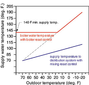
Boiler reset control alone is fine for systems using only high temperature hydronic heat emitters, like baseboard, panel radiators or certain "staple-up" floor heating installations. However, because conventional boilers require protection from sustained flue gas condensation, the water temperature they operate at can only be reduced so far?usually in the range of 140 degrees F outlet temperature. During mild weather, such a "partially reset" boiler still provides water to the system's primary loop that is higher than required by heat emitters. Room thermostats must be used to start and stop flow through the heat emitters to prevent overheating.
As implied by its name, mixing reset requires a mixing device between the primary circuit and a separate distribution circuit. Two-way, three-way or four-way valves can all serve as modulating mixing devices, as can a variable speed pump. The mixing device not only provides the proper supply water temperature to the distribution system, it also acts as a control gate to prevent the distribution systems from extracting heat faster than the boiler can produce it. Modern mixing reset controls allow the water temperature supplied to the heat emitters to be reduced right down to room temperature if necessary.
It's possible to combine boiler reset control with one or more mixing reset controls in the same system, provided the primary loop temperature is maintained somewhat above the highest required mixed supply temperature in the system. Boiler efficiency is maximized, as is comfort provided by the distribution system. Watch for a PME article in the near future that details how this works.
Figure 4 shows a typical reset line for a conventional gas-fired boiler, as well as for a low temperature floor heating system.
Putting It All Together
The schematic in Figure 5 shows many of the building blocks we've discussed merged into a single system.This system uses a staged multiple boiler system to supply several types of space heating, as well as domestic hot water, intermittent garage floor heating and even some areas of snow-melting.
Notice that the higher temperature space heating loads are placed near the beginning of the primary circuit, while those using mixing devices are placed near the end. The domestic water heater and heat exchangers for snow-melting and garage floor heating are piped as parallel circuits.
The water temperature in the primary circuit is controlled by the boiler staging control. During a "heating demand" from any of the space heating loads, the primary circuit rises to a temperature calculated by the staging control based on outside temperature (e.g. reset control). All space heating loads connected to the primary circuit receive reduced water temperature during warmer weather. The mixing devices reduce the water temperature to their respective loads based on their individual settings. During a "setpoint demand" from any of the loads supplied through heat exchangers (DHW, snow-melting, garage heating), the boiler loop rises to a fixed high temperature limit (say 200 degrees F), ensuring high rates of heat transfer through the operating heat exchangers.
The controls for such a system might also incorporate priority logic that could, for example, temporarily suspend heat to the snow-melting load or garage-heating load if the domestic water heater is calling for heat. Such strategies eliminate the need to size the heating plant for the total peek demand of all loads and generally improve the seasonal efficiency of the heat plant.
Not all modern multi-load systems are as complex as that shown in Figure 5. Still, by using the concepts discussed, informed designers can assemble a hydronic system for the exact needs of their client--a system that provides years of comfort and fuel efficiency using the unsurpassed ability of water to convey heat.

