
Criteria for valve selection is normally concerned with the service intended, pressure rating, cost, space considerations and maintenance convenience. However, such criteria can change for different conditions and must be considered when selecting a valve. Let me review some of these unusual conditions, beginning with valve pressure loss.

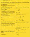
Calculation of Pressure Loss
Pressure loss test data for a large variety of valves and fittings are available from the work of numerous investigators, with the Crane Company laboratories in the forefront of many of them. Due to the time consuming and costly nature of such testing, information has not been done for all valves and fittings. The most commonly used designated symbols to accomplish this are the flow constant Cv.Pressure losses are the result of various conditions:
Cv is the basic and most widely used industry standard for determining flow capacity of a valve. It is defined as the number of gallons per minute (gpm) at 60°F that will pass through a full open valve with a pressure drop of 1 psi.
The Cv for water is usually determined experimentally. This can be physically determined by measuring the flow through a valve with 1 psi applied pressure to the valve inlet and have a 0 psi pressure at the outlet. A close approximation also can be found mathematically by dividing the water flow through the valve, in gpm, by the square root of the pressure drop in psi produced by that flow.
Conversely, given the Cv, the water flow through the valve at any pressure drop can be calculated by multiplying the Cv by the square root of the pressure drop. Thus, the higher the Cv number, the higher the rate of flow and the lower the friction loss through the valve. The Cv of a valve is dependent upon certain factors that are established by the manufacturer during actual testing. (See equations sidebar)
Valve Recovery
This term refers to the fact that downstream of the valve, the velocity slows down and the pressure increases (or “recovers”) from the lower pressures internal to the valve. When the velocity of the liquid increases within the internals of a valve, the pressure decreases. Internal to the valve there is a higher velocity than there is both upstream and downstream.The term “valve recovery” is usually applied when a valve is employed as a restriction. If using a valve to cause a pressure drop as compared to control the flow of volumes, it is safe to say that a low recovery valve will resist causing cavitation more than a high recovery type. It is a given that any valve could cause cavitation to a differing degree and in different closure positions. To predict if a valve will experience cavitation, certain valve manufacturers have conducted extensive testing and can be relied upon to provide a prediction and prevention information to users.
The valve recovery coefficient is a dimensionless, numerical factor that represents a valve’s flow vs. liquid pressure curve, and thus the valve’s tendency to cavitate. There is a desired flow vs. pressure profile through the valve. If this factor is higher than desired, cavitation might develop. The valve coefficient is affected by the internal geometry of the valve, valve size, pressure, and the presence or absence of piping reducers adjacent to the valve. The valve recovery coefficient is an experimentally developed figure obtained from the manufacturer.
Cavitation
Cavitation can occur only in liquids where atmospheric pressure on the surface of a liquid temporally drops below vapor pressure, causing a liquid to vaporize into vapor bubbles. As the bubbles move along their path toward a higher pressure, the bubbles will rapidly collapse (or implode) back into the liquid as the pressure increases downstream with a resulting shock wave that could cause damage to the valve closure surface. Cavitation is a condition found in valves mostly when they are used for pressure reduction [seeFigure 1].Cavitation is named because the energy of implosions is considerable and will chip (or corrode) the metal of the seat, causing cavities. As the temperature of the liquid increases, cavitation and flashing become more likely due to the increased vapor pressure. If downstream pressure is high, bubbles will not form. Downstream, there is a lower pressure caused by energy losses because of the restriction. This is how we achieve any pressure drop.
Cavitation or flashing occurs because the pressure energy in a fluid is converted to kinetic energy due to the contraction at the valve closure member, causing an increase in velocity. In addition, as the temperature of the liquid increases, the likelihood of cavitation becomes more likely because of the increased vapor pressure. The extent of the cavitation depends mainly on the downstream pressure and the differential pressure across the valve.
When the vapor bubbles collapse, the energy release is far different from that of a burst. Unlike a vapor bubble formed by boiling that bursts on the surface, a collapsing bubble actually changes back to a liquid state. Although heat is a minor part of this change of state, the shock waves generated by the collapse are the major forces generated and what cause the damage. This combination of highly concentrated energy and focused direction make the collapsing bubble very destructive. Even if the bubbles collapse adjacent to the surface of the valve and erosion is avoided, the shock waves can still cause vibration that may be harmful to the valve or piping system.
In cases where there are identical pressure drops between the upstream and downstream portions of a valve, there will be lower pressures internal to a butterfly valve than in a globe valve. Where the internal pressure of a high recovery valve and a low recovery valve is equal, the downstream pressure will be greater, by definition, for a high recovery valve.
Another situation arises where both the downstream pressure and the pressure drop are identical for a high recovery valve and a low recovery valve. The internal pressure inside the high recovery valve will fall to a lower value than it does inside a low recovery valve, and may, therefore, fall below the vapor pressure of the liquid. Thus, one valve type may experience cavitation while another, though providing the same pressure drop, will not. Yet another circumstance occurs where a high recovery valve may induce cavitation even though the pressure drop it creates is less than the pressure drop caused by a low recovery valve.
If using a valve for dropping pressure (as compared to one used to control the volume), it is safe to say that a low recovery valve will resist causing cavitation more so than a high recovery valve. Of course, all valves can cause cavitation to a different degree at different travel positions. To predict if any particular valve will experience this, manufacturers have performed extensive tests and can be relied upon to give this prediction to users.
We can design valves for optimum performance. It may be possible in a pressure control application to fit two or more high recovery valves in tandem, each taking an equal fraction of the drop across each valve. Also, some manufacturers have developed very effective trim, v-ports or other internals that resist both the onset and effect of cavitation.
If cavitation is ever encountered, consider the following corrective actions:
1. Use a valve with a low recovery coefficient.
2. Increase the downstream pressure by installing a flow restrictor if possible or reducing the pipe size of a short piece downstream.
Fire-Safe or Not
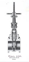
It may be necessary to minimize dangerous product leakage and maintain effective shutoff if a valve is subject to fire conditions. Valves that satisfy this condition are known as fire-safe. This term fire-safe is one of the least understood valve specifications. To date, there is no test protocol to establish whether a valve is fire-safe. The common definition used for a fire-safe valve is when a valve is exposed to fire conditions, it will allow minimal leakage through the seat and stem, and continue to provide effective shutoff during or following a fire or exposure to excessive temperatures. A typical example of a fire-safe valve is a gate valve [seeFigure 2].For the valves that the plumbing engineer uses, particularly for water, sprinkler and fire standpipe systems, the gate valve would be the preferred choice. A valve is considered fire-safe if, when exposed to fire conditions, it will have minimal leakage through the seat and stem when closed and will provide effective shutoff during a fire or exposure to excessive temperatures.
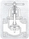
Gate and globe valves [see Figure 3] made from metals that do not melt during a catastrophic fire have also been classified as fire-safe. Their design and construction assured metal-to-metal seating before, during and after a fire. Butterfly valves are commonly manufactured with a “tandem” soft seat over metal to achieve a fire-safe application.
Manufacturers of ball, plug and butterfly valves developed soft- and hard-sealing elements that meet these needs. These types of valves provide metal-to-metal seating after a fire.
The “soft” seat valves have rubber, plastic or elastomeric compositions that have melting points below 700°F. The soft seats burn out during a fire and then use disk travel or gravity to maintain metal-to-metal contact after the fire. The seats are made of a hard material that can survive the temperatures. However, if the soft seats burn during a fire and they are not totally destroyed, the metal-to-metal contact may not occur.