
Figure
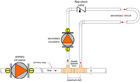
1. Hydraulic separation using a pair of closely spaced tees.
Keeping the tees as close as possible reduces the pressure differential between the beginning and end of the secondary circuit to almost zero. A flow check valve with a low opening pressure requirement is used to compensate for any slight pressure drop remaining between the tees as well as for buoyancy-induced heat migration. This ensures that no flow develops in the secondary circuit until its circulator is operating.
Figure
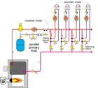
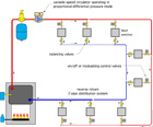
2. Schematic of a parallel primary loop used in systems where the same fluid
temperature must be supplied to each secondary circuit.
Primary Loop: Series or Parallel
P/S systems can have either series or parallel primary loops. In a series primary loop system, each secondary circuit connects to the primary loop in sequence. The first secondary circuit receives the highest temperature water, the next secondary circuit downstream gets water that’s slightly cooler, and so on. The drop in temperature from one secondary circuit to the next should be accounted for as the system is designed.Loads requiring higher supply temperatures should be connected near the beginning of the primary loop, while those capable of operating at lower supply temperatures are connected near the end of the primary loop. Even with this arrangement, water-supply temperatures to a given secondary circuit can vary depending on which secondary circuits are operating at a given time.
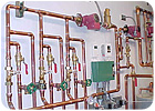
A parallel primary loop is used in systems where the same fluid temperature must be supplied to each secondary circuit. A schematic of this piping configuration is shown in Figure 2, and an installation photo is shown in Figure 3.
The benefit of equal supply temperature comes at the cost of more complex and expensive piping relative to a series primary loop. Each crossover bridge in the parallel primary loop is equipped with a balancing valve so flow through that bridge can be set in proportion to the secondary circuit load it serves. These valves add cost and may or may not be properly adjusted once the system is in service.
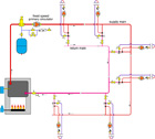
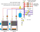
In some applications, parallel primary loops extend well beyond the mechanical room. They might encircle the interior perimeter of a large building, as depicted in Figure 4.
Notice that the parallel primary loop in Figure 4 is piped in reverse return to help balance flows through crossover bridges. However, there is no guarantee that any reverse return piping system is completely “self-balancing.” Good practice still requires that a balancing valve is installed in each crossover bridge to “fine-tune” flows in proportion to secondary circuit loads.
Figure
3. Photo of a parallel primary loop used in systems where the same fluid
temperature must be supplied to each secondary circuit. Photo courtesy of Mike
Reif.
Traditional parallel P/S systems use a fixed-speed primary circulator that operates whenever one or more of the secondary circuits are on. Once the system is balanced, flow through all the mains and crossovers remains constant regardless of which secondary circuits are operating. This approach presents no opportunity to reduce the power consumption of the primary circulator under partial-load conditions.
Since flow in a parallel primary loop is not modulated with control valves, a variable-speed circulator operated by a differential pressure controller does not make sense as the primary circulator. However, it is possible to use a variable-speed circulator controlled by the temperature difference between the supply and return sides of the primary loop. As individual load circuits turn off or modulate down in capacity, the differential temperature across the primary loop decreases. Upon sensing this, the controller reduces the speed of the primary circulator in an attempt to maintain a set temperature drop across the loop.
Figure
4. Schematic of parallel primary loop encircling the interior perimeter of a
large building.
Alternatives Abound
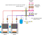
The classic alternative to a parallel primary loop that encircles a building is a two-pipe reverse return system. In the past, these systems have used a single fixed-speed circulator to provide all flow in the system. A differential pressure bypass valve (DPBV) was installed to compensate for changes in differential pressure across the mains as zone valves in branch circuits turned on and off, or as branch flow was throttled by modulating valves.Although DPBVs do limit differential pressure, they do so by throttling away excess head energy created by the fixed-speed circulator. This is like pressing the gas pedal and brake pedal of a car at the same time. The net effect may be desirable, but it’s not the most energy-efficient approach.
Today this type of system can be equipped with a variable-speed circulator that automatically senses changes in differential pressure across the system and reacts accordingly. Any attempted increase in differential pressure is quickly countered by a decrease in motor speed. Reducing circulator speed under partial-load conditions decreases electrical energy consumption dramatically. Some studies indicate energy savings of 65% to 80%. This approach also eliminates the need for a differential pressure bypass valve and flow check valves in each branch. An example of this concept is shown in Figure 5.
A two-pipe reverse return system will not provide the same “pure” hydraulic separation between all load branches as does a parallel primary loop. However, the use of a properly configured variable-speed circulator controlled based on pressure differential can approximate this condition. The greater the “authority” (e.g., pressure drop) of the branch circuits relative to the main piping, the better this approximation becomes.
Figure
5. Two-pipe reverse return system eliminates the need for a differential
pressure bypass valve and flow check valves in each branch.
Close Proximity
There are many systems where individual load circuits begin and end within the mechanical room rather than at locations out in the building. Such situations present several options to parallel primary loops. One alternative is shown in Figure 6.Here the boiler system is connected to a large-diameter vertical header within a relatively compact space. Boiler piping is hydraulically separated from the vertical header using a pair of closely spaced tees. The generous diameter of the header and relatively close spacing between all supply and return connections results in a very low pressure drop between points A and B. Low enough that each load circuit is hydraulically separated from the others.
Figure
6. Schematic of a boiler system
connected to a large-diameter vertical header within a relatively compact space.
Another option is to use a hydraulic separator between the boilers and the load circuit, as shown in Figure 7. The low vertical velocity in this device produces minimal pressure drop top to bottom, as well as side to side. This results in hydraulic separation between the boiler circuits and load circuits, as well as efficient air and dirt removal. This eliminates the need for separate devices for the latter two functions.
Figure
7. A hydraulic separator located between the boilers and the load circuit.
Lose The Pump
A major advantage of using the piping methods shown in Figures 5, 6 and 7 rather than a parallel primary loop is elimination of the primary loop circulator. This reduces both installation and life-cycle operating cost. The latter is often several times greater than the former. Even with fractional-horsepower circulators in small commercial installations, these savings can be several thousands of dollars. Here’s an example:Consider a system that supplies 500,000 Btu/hr at design load conditions. Design flow in the primary loop is 50 gpm with a corresponding head loss of 15 feet (6.35 psi pressure drop). Assume a wet rotor circulator with wire-to-water efficiency of 25 is used as the primary circulator in this system.

Equation
1

Equation
2
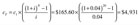
Equation
3
This, combined with eliminating the multi-hundred-dollar installation cost of the primary circulator, obviously results in significant savings for the client.
Conclusion
Although I’ve designed primary parallel loops into several systems, and they’ve consistently delivered both hydraulic separation and equal supply temperature to the loads, the alternatives we’ve discussed offer virtually the same benefits and significantly reduced cost.Given that boiler efficiency is now very close to theoretical limits, reducing the power consumption of distribution systems will likely become the focus of efforts to improve the overall efficiency of hydronic systems. In this regard, parallel primary/secondary piping systems will play a diminishing role relative to the alternatives.
