Note: This article is mainly comprised of excerpts from a recent study prepared by Professor John Swaffield and Dr. Michael Gormley of Heriot-Watt University in Scotland titledBuilding Drainage Waste and Vent Systems: Options for Efficient Pressure Control. Copies of this study can be obtained by contacting Studor, Inc. at (800) 447-4721.
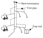
Figure1. Fully vented system with open top and parallel vent pipe.
At the center of the drainage system’s integrity is the water trap seal, which stops sewer gas from entering a habitable space from the sewer. The water trap seal is usually 2 inches in depth depending on the fixture it is protecting.
It comes as a surprise to many that the flow of air is as important, if not more important, to the safe operation of the drainage system as the flow of water. This air flow is ‘induced’ or ‘entrained’ by the flow of water. The unsteady nature of the water flows causes pressure fluctuations (known as pressure transients), which can compromise water trap seals and provide a path for sewer gases to enter the habitable space.
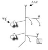
Figure 2. Two-story house with AAVs on branches and AAV termination at the top of the stack.
Pressure Transients
Transients can be dealt with by a combination of careful design and the introduction of pressure control devices as close to the area of concern as possible. Long vent pipes can be an inefficient way of providing relief due to friction in the pipe. Distributing air supply inlets using air admittance valves (AAVs) around a building provides an efficient means of venting by allowing air to enter the system, and they also reduce the risk of positive transient generation. AAVs do not cause positive pressure transients, they merely respond to them by closing, and hence, reflect a reduced amplitude wave.The introduction of a positive air pressure transient alleviation device known as the Positive Air Pressure Attenuator (PAPA) provides a means to ‘blow off’ pressure surges as close as possible to their source, thereby protecting water traps. Attenuation of up to 90% of the incident wave can be achieved, thus protecting the entire system. It should be noted that there is little that can be done for a system experiencing a total blockage, generating excessive static positive pressures in the drainage system. In such circumstances, the lowest water trap seal will ‘blow’-providing relief for the whole system. This will occur regardless of the method of venting employed.
In validated test simulations, AAVs have been shown to provide at least as good protection for water trap seals as a system completely vented with piping to the outdoors, and in tall buildings in some circumstances, AAVs provide even better protection. The fully engineered designed active control system utilizing AAVs for negative pressure relief and PAPAs for positive transient relief is shown to be an effective method for balancing the need for safety and efficiency while maintaining functionality invisible to the user.
A negative pressure transient communicates a need for more air and represents a suction force, while a positive pressure transient communicates the need to reduce the air flowing and represents a pushing force. A negative transient can be caused by air leaving the system (hence the need for more air), and a positive transient can be caused by the air reaching a closed end (stopping the air where there is no escape route).
A negative transient will attempt to suck water out of a water trap seal. The pressure differential may not be sufficient to completely evacuate the water the first time, but the effect can be cumulative. Positive air pressure transients cause air to be forced through the water seal from the sewer side to the habitable space inside.
The need to communicate an increase or decrease in the air-flow and the finite time that this takes is central to the requirements of providing a safely engineered drainage system. The absolute key to maintaining a state of equilibrium in a drainage system is to provide pressure relief as close to where it will occur as possible. If negative pressure transients are a call for more air, then positive pressure transients are a call to stop sending air.
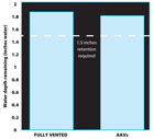
Figure 3. Comparison of water retained in the ground floor trap (shaded on schematic of Figure 4.)
Modeling Flows in Drainage Networks
Research and analysis of real building drainage systems is complicated by the difficulty in obtaining data from ‘live’ buildings. Most areas of engineering employ some form of modeling technique in research and development in their ‘look and see’ approach to development. In DWV research, there are few models capable of dealing with the complex time-dependent transient flows.The computer model AIRNET, developed by Professor John Swaffield, Heriot-Watt University (Scotland), is capable of such a complex task. At the heart of the AIRNET model is the mathematical technique known as the method of characteristics. The technique allows the propagation of waves to be predicted along the length of a pipe at different time steps. This is a very powerful and unique way to ‘look and see’ what is actually going on inside a building drainage system. The simulations (discussed on the following page) in a specific study were carried out using AIRNET.
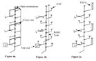
Figure 4. Three installation types in 10-story building simulation.
Two-Story Building Simulation
A two-story building drainage system can operate sufficiently well with minimal additional ventilation as long as it is designed and installed properly. This is borne out by reference to the installation shown inFigure 1andFigure 2. The building represents a fairly common house with a number of bathrooms and a group branch in a kitchen/laundry area. The simulation was run in two different scenarios:1. System with an open pipe vent
2. System with AAVs
A discharge flow rate was simulated from the top floor consisting of a combined flow from a WC and a bath. This discharge was simulated from the upper floor and the effect on the water trap indicated by shading was recorded from the output data. It can be seen from the bar graph shown inFigure 3that little water has been lost as a result of the operation of system devices in either scenario.
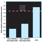
Figure 5. Comparison of water retained in the lowest water trap (shaded on schematic in Figure 4.) Conditions based on negative transient.
10-Story Building Simulation
The 10-story building scenario is shown in the variations ofFigure 4.There are basically three installation types being simulated here. The first is a fully vented system (see Figure 4a). The second is a one-pipe system with distributed venting and an AAV on the top of the stack (see Figure 4b). This system also includes a relief vent. The third (Figure 4c) is the one-pipe system with distributed AAVs and PAPAs subjected to a positive air pressure transient simulated to replicate the occurrence of a surcharge in the sewer. In each of the scenarios a representative water trap is shown on three floors in the building.The flow rate used in this simulation represents a maximum for the 4" vertical stack in question (80 gpm). This flow rate is unlikely to be observed in practice, as the simultaneous discharges required are a probabilistic impossibility (Hunter 1940). The flow rate is therefore indicative of a ‘worst case scenario’ in order to push the drainage vent system to its limits, and therefore show comparisons between the options investigated. The discharges making up the flow rate are distributed evenly along the stack to simulate a number of simultaneous discharges (approximately 16 gpm from five different floors).
The bar graph shown inFigure 5 illustrates the water depth retained in the shaded water trap in Figure 4 following this event. It can be seen that under these conditions, the system with AAVs installed (Figure 4b) has retained more water than the open pipe system (Figure 4a). Why is this? The main reason is that the flow in the vertical stack induces a negative pressure transient as it calls for more air. This negative transient propagates to all parts of the system “looking for air.” The negative transient represents a suction force that will try to draw water out of the trap seal. If the negative transient is too great, it will suck water out of the trap. To stop this happening, air must be provided from somewhere else.
Two different methods are shown in Figure 4a and Figure 4b. In Figure 4a, the air must travel from the top of the stack, approximately 100 feet away (but only after the negative transient has propagated to the top of the stack first, so the round trip is approximately 200 feet). Alternatively, air can be provided locally by the provision of an AAV (Figure 4b). In this case the round trip is only a matter of 10 feet. This means that the air can be provided quicker than with the fully vented system.
Figure 6shows the trap retention on the same trap as the result of a positive pressure transient in the system. The positive transient was generated by simulating a surcharge in the sewer, causing the airflow through the stack to be stopped. Again, there are three methods of dealing with this scenario: the fully vented system shown in Figure 4a and the ‘active control’ option utilizing AAVs and PAPAs as shown in Figures 4b and 4c. The bar graph of trap retention clearly shows that the active control system shown in Figure 4c provides the best protection against this sort of event, and that the AAV system with a relief vent shown in Figure 4b provides better protection than the fully vented system in Figure 4a.
The reasons for active control being better are two-fold: first, the distribution of the air inlets reduces the maximum positive pressure possible; and second, the PAPA presents a volume that can consume the positive pressure wave, attenuate it and destroy it, rendering it harmless. This is borne out by the amount of water displaced by the positive pressure wave.

Figure 6. Comparison of water retained in the ground floor trap indicated (shaded on shematic in Figure 4). Condition based on positive transient.
Conclusion
Air admittance valves (AAVs) have been installed worldwide since the early 1970s and in North America since 1989. Millions of valves have been installed; they have been field-tested and are operating successfully. The Positive Air Pressure Attenuator (PAPA), which was invented by Professor John Swaffield and Dr. David Campbell of Heriot-Watt University, Scotland, was introduced in North America in 2004.Since their introduction, five major high-rise buildings (with AAVs and PAPAs installed) have been completed in the U.S., and there are six more projects under construction in which AAVs and PAPAs have been specified. In addition to U.S. installations, AAVs and PAPA systems are being installed on a regular basis worldwide. Design professionals have realized that these “active pressure control devices” are a viable option to open pipe venting and Sovent® systems.