Looking back at the history of residential hydronic heating in North America over the last 25 years, one is amazed at the progress made in the area of thermal efficiency.
For example, I grew up in a 1960s vintage ranch house heated by an oil-fired steel fire tube boiler. The boiler was equipped with a tankless coil for domestic water heating. Upstairs was a single thermostat that controlled the entire 1,500-square-foot house.
When I replaced that boiler in 1989, the fire tube baffles were completely burned away. This helped explain the net stack temperature of about 550°F. Although this boiler kept our house comfortable for over 30 years, its "aged"

As Good As It Gets?
One might conclude that our industry has just about hit the limit of what's theoretically possible with converting fuel into heat. That little remains to be accomplished in terms of efficiency improvements. But just as an oasis fades away when you're just about to it, so does this illusion of nearly perfect efficiency.True, the thermal efficiency of many modern boilers is very high, but a hydronic system is more than a high-performance boiler. The distribution efficiency at which many current hydronic systems convey heat from the heat source to the heat emitters provides plenty of room for improvement.
Let's define distribution efficiency.

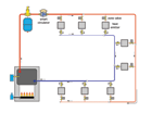
Here's an example: Consider a hydronic system that delivers 120,000 Btu/hr at design load conditions using four circulators operating at 85 watts each. The distribution efficiency of that system is listed in the following equation.


It's hard to judge a number for distribution efficiency without something to compare it to. Here's a similar calculation for a furnace with a blower that operates at 850 watts while delivering 80,000 Btu/hr through a forced air ducting system, as shown in the following equation.
For these examples, the hydronic system provides a delivery efficiency about 3.8 times higher than that of the forced air system. This is not uncommon for many current day installations. It's a direct result of water being far superior to air as a media for absorbing and carrying heat.
So, how can we further improve the distribution efficiency of hydronic systems? Here are some things I think will help the North American hydronics industry get more Btu/hr delivered per watt of electrical pump power.
1. Use higher temperature drops: As designers, we have to stop thinking that water "wants"

Where:
P1 = power required at flow rate f1
P2 = power required at flow rate f2
According to this equation, operating a circulator at 50% of design flow would (in theory) require only 12.5% of design load power input. Actual savings will be less due to non-proportional losses in bearings, motor windings, etc., but very significant savings are still waiting for those who recognize the physics of moving water through piping systems, and take advantage of it in their designs.
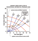
Another way to increase distribution efficiency is to improve the way the "head source"

sm.gif)
Both constant differential pressure and proportional pressure control modes eliminate the need for a differential pressure bypass valve. Such valves are currently regarded as the standard approach to controlling the symptoms of fluctuating differential pressure in zoned systems with fixed speed circulators. Smart circulators address the cause rather than the symptoms of the problem (excessive head input under partial load conditions). In doing so, the symptoms of excessive differential pressure (flow noise, erosion corrosion, and valve stem lift) are eliminated, while considerable energy savings are also achieved. The cost savings from not having to purchase and install a differential pressure bypass valve obviously reduces the incrementally higher cost of the smart circulator.
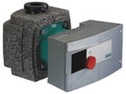
Some smart pumps can also compensate for changes in water temperature associated with outdoor reset control, and even nighttime setback. The circulator contains an internal temperature sensor that constantly measures water temperature to (or in some cases from) the distribution system.
The Bottom Line
Estimated energy savings vary according to the specifics of the load as well as the operating mode of the circulator. Simulations done in Europe project savings in electrical usage of 50% to 80% relative to an uncontrolled fixed speed circulator of equivalent performance.One manufacturer estimates that converting all small circulators (under 250 watts peak) in the European Union to current generation smart circulators has the potential for saving 10 billion kilowatt-hours per year! Although similar projections for the North American market are yet to be made, there is little doubt that savings in both new and retrofit installations will be profound. Payback periods of four years or less are likely, with a projected 20-year life-cycle cost of a smart circulator approaching half that of an uncontrolled fixed speed circulator.
Several manufacturers currently offer small smart circulators in the European market, and this is finally being noticed in North America. Just as the concept of smaller modulating boilers made its way from Europe to North America, it's inevitable that smart circulators will capture the attention of cutting edge hydronic designers, as well as their clients who are presented with the economic advantages.
Current generation wet rotor circulators will surely remain in the market for the foreseeable future, but will decline in market share as our industry and its customers grasp the energy-saving implications of the next generation of smart circulators. The eventual impact these circulators will make on the North American market will likely rival that of modern high-performance boilers versus their predecessors. Get ready, because big changes in small circulators lie just ahead. Together with careful refinements in piping design, these new circulators will greatly improve the distribution efficiency of present day hydronic systems.
