This article shows how to apply the analytical concept of hydraulic resistance to analyze the hydraulic and thermal performance of systems using "diverter tees."
Issue: 6/05
Ask anyone who's been involved in hydronic heating for a few decades if they know what a "Monoflo® system"
|
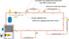
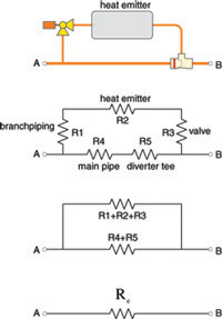
| FIGURE 1 |
Diversionary Thinking
Diverter tee systems are an upgrade from basic series piping circuits. They allow each heat emitter served by a single piping loop to be independently controlled. Each heat emitter is piped into a branch piping path as shown in Figure 1.
A portion of the flow entering the upstream tee is diverted through the branch circuit (assuming the flow path through the branch is not blocked by a closed valve). The "enticement"
|
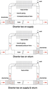
| FIGURE 2 |
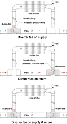
If a single diverter tee is installed in the upstream location, the pressure drop is created by the truncated cone orifice inside the tee (see Figure 2). One can think of this tee as a "scoop"
|
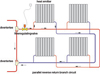
| FIGURE 3 |
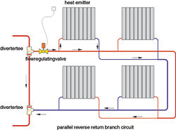
Diverter tees can also be used to supply a piping subassembly such as the one shown in Figure 3. In this case, the subassembly is a group of four panel radiators, all located in the same heated space. The radiators are connected in a parallel reverse-return arrangement to ensure the same supply temperature and reduce head loss. A single flow-regulating valve serves the group.
|
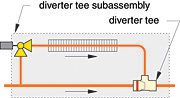
| FIGURE 4 |
By the Numbers
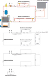
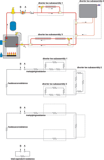
The hydraulic analysis of diverter tee systems is more complex than that of simple series circuits. This is due to the parallel flow paths at each location where a heat emitter is connected to the main piping circuit. Such locations can be enveloped into a diverter tee subassembly that begins just upstream of the first tee and ends just downstream of the second tee. An example is shown in Figure 4.
|
| FIGURE 5 |
This subassembly can be modeled using hydraulic resistors, as shown in Figure 5.
Each resistor symbol represents the hydraulic resistance of a portion of the subassembly, such as the common piping between the tees, the diverter tee(s), and the resistance of the heat emitter in the branch circuit.
As in electrical circuit theory, hydraulic resistors can be combined into "equivalent resistors"
|
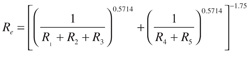
| EQUATION 1 |
Re = the equivalent hydraulic resistance of the diverter tee subassembly
R1 - R5 = the hydraulic resistance of the piping segments, fittings, valves, and heat emitter
0.5714, and -1.75 are exponents
The exponents in Equation 1 are based on the use of smooth (copper) tubing, and are not applicable to rougher steel or black iron piping assemblies.
Values for the hydraulic resistance of the piping segments, fittings, and heat emitter can be computed using Equation 2 and its associated data.

|
| EQUATION 2 |
R = hydraulic resistance of a given component
a = fluid properties factor (see Equation 3)
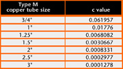
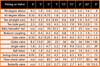
c = a constant based on pipe type and size (see Figure 6)
l = equivalent length of the pipe, fitting for valve (see Figure 7)
Note: When two diverter tees are used, double the equivalent length of a single diverter tee.
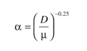
The value of the fluid properties factor a can be found using Equation 3, evaluated at the average temperature of the system fluid.
|
| EQUATION 3 |
Where:
a = fluid properties factor
D = density of the fluid at the average system operating temperature (lb/ft3)
u = dynamic viscosity of the fluid at the average system operating temperature (lb/ft/sec)
-0.25 = an exponent
|
| FIGURE 6 |
The equivalent length of various fittings and valves, including available sizes of Bell & Gossett Monoflo tees, are given in Figure 7.
|
| FIGURE 7 |
Putting It All Together
Once a diverter tee subassembly has been reduced to a single hydraulic resistor, it can be combined in series, with the other hydraulic resistors representing the piping and other flow elements in the main piping loop. This group of resistors can then be reduced to a single equivalent resistor that allows the system curve for the overall distribution system to be generated using Equation 4. The concept is shown in Figure 8.
|
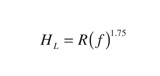
| EQUATION 4 |
Where:
HL = head loss of distribution system (feet of head)
R = overall equivalent resistance of distribution system
f = flow rate through distribution system (gpm)
Once the system curve is established, the pump curve for a "candidate circulator"
|
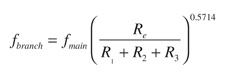
| EQUATION 5 |
cU?°?5
Where:
fbranch = flow rate through branch containing heat emitter (gpm)
fmain = flow rate upstream of diverter tee subassembly (gpm)
Re = equivalent hydraulic resistance of diverter tee subassembly (from Equation 1)
R1 + R2 + R3 = total hydraulic resistance of branch circuit
0.5714 = exponent
Once the flow through the branch is determined, it can be combined with the inlet temperature to that branch to determine the heat output from the heat emitter. This will require a model of heat output from the heat emitter based on flow rate and inlet fluid temperature.
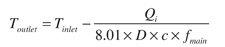
The outlet temperature from a diverter tee subassembly can be determined using Equation 6.
|
| EQUATION 6 |
Where:
Toutlet = temperature of fluid leaving the diverter tee subassembly
Tinlet = temperature of fluid entering the diverter tee subassembly
Qi = heat output of heat emitter in branch (Btu/hr)
D = density of the fluid at the average system operating temperature (lb/ft3)
c = specific heat of the fluid at the average system operating temperature (Btu/lb/
|
| FIGURE 8 |
The analytical methods described here allow for detailed hydraulic and thermal analysis of diverter tee systems that have the piping topology given in Figure 1. They allow different heat emitters as well as unlimited choices of branch piping configuration to be simulated as a single system. Having such versatility, however, does add to "mathematical overhead."
MEC Seminars Qualify for CECs
The BNP Media seminar series, Modern Engineering Concepts for Hydronic Heating Design, now qualifies for continuing education credits (Profession Development Hours) in the following states:
- Illinois, June 21
- Oregon, July 13
- Montana, July 15
The seminar, developed and presented by John Siegenthaler, P.E., presents the latest concepts in hydronic heating design for custom residential and light commercial buildings. Attendees receive an extensive seminar manual as well as design software and reference information on the seminar CD. Licensed engineers who would like to register for these seminars can do so at www.bnpmedia.com/mec-registration.html, or by calling 1-888-530-6714.
