There have been various methods devised for the sizing of water hammer arresters. These methods have created confusion regarding the proper sizing and location of water hammer arresters among engineers, contractors, and other persons engaged in the plumbing industry. To help clear up the confusion, the following article was excerpted from the pertinent sections of the Plumbing & Drainage Institute's Standard PDI-WH201, Water Hammer Arresters.
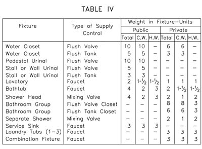
Table 1
Sizing and Placement Data
The members of PDI set out to establish a uniform method of sizing for water hammer arresters. They sponsored a research and testing program with the intention of producing one standardized method of sizing and placement. Such a method would benefit the entire plumbing industry.
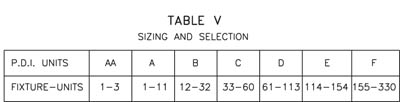
Table 2
PDI developed a protocol for identifying the various sizes of water hammer arresters. There were seven different sizes of water hammer arresters developed. It was decided to identify the arrester size by a code or symbol. The size was to be based on the capacity of the arrester to control the shock wave in different piping systems. The following symbols, AA, A, B, C, D, E, and F, have been devised to denote the range in sizes for water hammer arresters. "AA"
Example 1
When PDI certifies and lists a water hammer arrester, each size is designated by one of the symbols to identify the appropriate size in accordance with Standard PDI-WH201.

Example 2
Plumbing engineers are most familiar with sizing a water distribution system by use of the fixture unit method. Because this is a familiar method of sizing, PDI used this method for sizing water hammer arresters. The sizing method is quick and easy using fixture units. A water supply fixture unit is defined as a non-dimensional unit of the probability of simultaneous use of water in a plumbing water distribution system.

Figure 1
Table 1 lists the fixture unit values for various fixtures for both hot and cold water supply. This table is used in PDI-WH201 when sizing water hammer arresters.

Figure 2
These fixture unit values are the common values that most engineers utilize to size their water distribution systems. These values can be used in the sizing and placement of engineered water hammer arresters at the same time that the piping systems are sized.
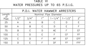
Table 3
In most installations where there are several fixtures, usually only one fixture valve at a time will be closed. Nevertheless, occasionally two or more fixture valves could be closed at the same instant. Table 2 on sizing and selection takes into consideration all design factors, including simultaneous usage, pipe size, length, flow pressure and velocity. Table 2, therefore, provides an easy, accurate method of determining the proper sized water hammer arrester for each multiple fixture branch line, and automatically provides for all factors that must be considered or otherwise calculated.
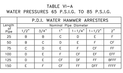
Table 4
After calculating the fixture unit load for a given branch, Table 2 can be used for sizing the water hammer arrester. This table would apply to both hot and cold water. This table is based on a maximum water pressure in the branch of 55 psi. When the pressure in the branch exceeds 55 psi, the water hammer arrester should be increased by one size. For example, a "C"
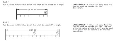
Figure 3
Examples
Table 2 will permit engineers and contractors to select the proper water hammer arrester for each application. Examples 1 and 2 show the relative ease with which sizing can be accomplished using Tables 3 and 4.
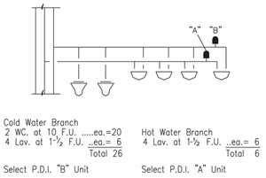
It is relatively easy to select the proper sized water hammer arrester for a multiple fixture branch. Figure 1 represents a typical riser diagram of the type that an engineer may include with his set of drawings.
When sizing the cold and hot water branch lines, the total fixture unit load is established for each branch line. This information is then applied to sizing charts to determine the required size of the branch lines.
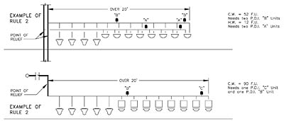
Examples of Rule 2
The proper sized water hammer arresters can be selected once the total of fixture units for a cold or hot water branch line is known. It is only necessary to apply the fixture units to Table 2 and select the appropriate water hammer arrester.
It is suggested that the engineers identify the water hammer arresters by the PDI symbols on the riser diagrams, as shown in the illustration. This will assure that the contractor will provide the correct size when installing the water distribution system.
The recommended location for the water hammer arrester is at the end of the branch line between the last two fixtures served. This location is shown in Figure 2.
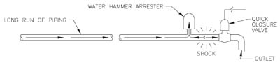
Figure 5
The location of the water hammer arresters shown in Figure 2 applies to branch lines that do not exceed 20 feet in length, from the start of the horizontal branch line to the last fixture supply on this branch line. When the branch line exceeds the 20-foot length, an additional water hammer arrester must be installed. The location of the water hammer arresters is based on experience in the industry as developed by PDI.
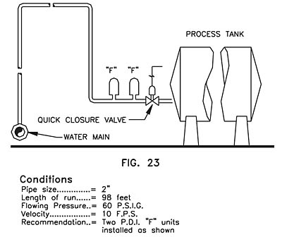
Figure 6
Long Runs of Piping to Equipment
The majority of sizing and selection applications will involve single and multiple fixture branch lines. These are easily handled with Table 2. The remainder of applications involves individual runs of piping to a remote item of equipment. The properly sized water hammer arresters for such applications can be determined by using Tables 3 and 4.
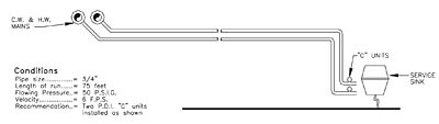
Figure 7
When long runs of piping are employed to serve a remote item of equipment, the water hammer arrester should be located as close as possible to the point of quick closure. At this location, the water hammer arrester will control the developed energy and prevent the shock wave from surging through the piping system. A typical example of placement is given in Figure 3.
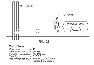
Figure 8
Examples defining the sizing and placement of water hammer arresters for single fixture and equipment branch lines are illustrated in Figures 5-8. For the sake of clarity, control valves, vacuum breakers and other necessary devices have been omitted in the illustrations.