
Issue: 2/05
The National Fuel Gas Code is the result of the American Gas Association, the American Society of Mechanical Engineers, and the National Fire Protection Association joining together to combine various standards into a single entity. The code offers general criteria for the installation and operation of gas-fired equipment, including venting.
There are many reasons you should follow the guidelines of the National Fuel Gas Code when venting gas-fired appliances. First and foremost, the products of combustion include carbon monoxide (CO). When improperly vented from the building, these products could be potentially fatal to the building occupants-leaving you liable. In addition, improper venting could result in premature failure of both the vent and hydronic equipment from condensation formation inside the vent. These problems can be prevented by following all guidelines in the National Fuel Gas Code and the equipment manufacturer's installation requirements.
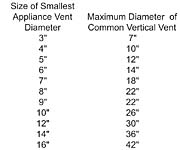
When applying the National Fuel Gas Code to the venting system of a hydronic heating installation, most designers think of the vent tables contained within the code. The National Fuel Gas Code vent tables dictate vent diameter based on the installation's total vent length (horizontal and vertical runs) and total Btus of the equipment. However, venting the products of combustion from a hydronic heating boiler involves much more than the information contained inside these vent tables. In this article, we will explore seven typical violations of the National Fuel Gas Code when common venting multiple hydronic appliances.
Seven Common Venting Installation Violations
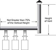
1. Venting Draft hood Equipment (NFPA 54, Section 10.6.1.4)-When venting draft hood equipment (which uses Type B or Type L vent material), horizontal runs shall not be more than 75% of the total vertical height of the vent (Figure 1).
Example: 100 ft. total vent height. Horizontal run cannot be more than 75 ft.

Example: Commonly seen in the field is a natural draft, Category I appliance vented into a common vent with a Category IV vented appliance. This directly violates the National Fuel Gas Code, since they are operating under different pressures. (See "SIDEBAR: Vent Category Definitions"
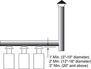
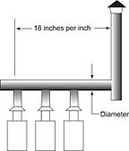
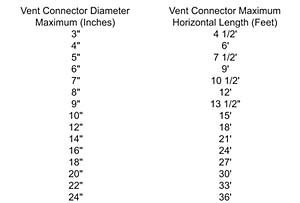
Example: If the common vent manifold connector diameter is 3-10 inches, the connector height must be at least one foot. If the common vent manifold connector diameter is 12-18 inches, the connector height must be at least two feet. If the common vent manifold connector diameter is 20 inches or larger, the connector diameter must be at least four feet.

Category I vented appliances may be vented into a masonry chimney lined with clay flue lining, fireclay brick, or other listed chimney lining systems that satisfy the requirements outlined in NFPA 211.
Category II, III & IV vented appliances may be vented into a masonry chimney lined with special gas vents listed for installation within masonry chimneys, as stated in NFPA 211.
All seven of these typical violations of the National Fuel Gas Code when venting multiple appliances into a common vent may be avoided or corrected by installing a mechanical draft system. These systems are installed to provide a positive draft and ensure that the products of combustion are taken out of the building regardless of the vent system installation conditions.
By design, mechanical draft systems maintain the necessary draft inside a vent system regardless of the number of appliances firing. This is achieved by modulating the input of a chimney automation fan located at the common vent outlet. This fan will increase or decrease the speed of exhaust based on the draft inside the vent, constantly maintaining the specified draft for proper operation.
Since all appliances common vented together do not always fire at once, another benefit of a mechanical draft system exists. Typically, for 80% of the heating season, a building will only need 20% of the heat output of the boiler system, failing to fully utilize the full Btu load the vent system was designed to handle. When this happens and the stack temperatures fail to rise above the dew point, condensation will occur in the vent. Condensation can be fatal to both the vent system and the boiler(s).
There are many risks when you fail to properly vent gas-fired appliances. Make sure that you are educated on the latest venting trends from your water heater and boiler manufacturer, and national and local codes. For additional information about the National Fuel Gas Code, visit www.NFPA.org.
SIDEBAR: Definition of Vent Categories
Category I-Appliance operating with a negative vent static pressure and with a flue gas temperature above dew point, avoiding condensate production in the vent.Examples: Draft hood and draft diverter vented appliances and fan-assisted equipment below 84% thermal efficiency.
Category II-Appliance operating with a negative vent static pressure and with a flue gas temperature below dew point, causing condensate production in the vent.
Examples: Fan-assisted appliances above 84% thermal efficiency.
Category III-Appliance operating with a positive vent static pressure and with a flue gas temperature above dew point, avoiding condensate production in the vent.
Examples: Forced-draft appliances and scotch marine-type boilers.
Category IV-Appliance operating with a positive vent static pressure and with a flue gas temperature below dew point, causing condensate production in the vent.
Examples: High-efficiency condensing appliances.

