How do you size expansion tanks for larger closed-loop radiant heating systems? Chances are you use the same methods you would for other hydronic systems. The classic sizing procedure for a diaphragm-type expansion tank compares the volume of the system's fluid when the system is at it highest temperature to the fluid volume when the system is first filled. An expansion tank volume is then calculated to accept the increased volume without allowing the system pressure to climb high enough to open the relief valve.
Here's a quick review of that classic sizing procedure.
Start by estimating the system's fluid volume (exclusive of the expansion tank). The data in Table 1 can be used to estimate the volume of the system's piping.
Table 1
Pipe gallons/foot
3/8" copper 0.008272
1/2" copper 0.01319
3/4" copper 0.02685
1" copper 0.0454
1.25" copper 0.06804
1.5" copper 0.09505
2" copper 0.1647
2.5" copper 0.2543
3" copper 0.3630
Pipe gallons/foot
3/8" PEX 0.005294
1/2" PEX 0.009609
5/8" PEX 0.01393
3/4" PEX 0.01894
1" PEX 0.03128
1.25" PEX 0.04668
1.5" PEX 0.06516
2" PEX 0.1116
Pipe gallons/foot
3/8" PEX-AL-PEX 0.004890
1/2" PEX-AL-PEX 0.01038
5/8" PEX-AL-PEX 0.01658
3/4" PEX-AL-PEX 0.02654
1" PEX-AL-PEX 0.04351

Formula 1, where:
V = volume of one foot of the tubing (gallons/foot)
di = exact inside diameter of the tubing (inches)
You'll also need to look up the fluid volume contained in the system's heat source. Most boiler manufacturers provide this data in their technical literature.
Add the tubing/piping volume to that of the heat source and any other miscellaneous system components (buffer tank, heat exchangers, etc.) to get the total estimated system volume (Vs).
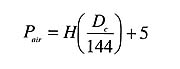
Formula 2, where:
Pair = the required air side pressure (before adding water to the system) (psi)
H = the height of liquid in the system above the inlet to the expansion tank (feet)
Dc = the density of the system fluid at its initial (cold) fill temperature (lb/ft3)
5 = an allowance for 5 psi static pressure at top of system
Formula 2 can be used for systems containing either water or antifreeze solutions. It requires the density of the "cold" fluid used to fill the system. The density of water at 60 degrees F is 62.36 lb/ft3. For other fluids look up their density at 60 degrees F.
The number 5 at the end of Formula 2 assumes that 5 psi of static pressure is desirable at the top of the distribution system for proper air venting and to suppress vapor pockets in high temperature applications. This number can be adjusted up or down. Higher values will result in larger expansion tank sizes and vice versa.
Once the air side pressurization is determined, the air side of the tank should be set to this value. Doing so ensures that the diaphragm will not be partially compressed when the system is filled with cool fluid, and hence, reduce the acceptance volume of the tank when the fluid expands under heating.
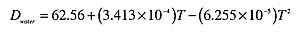
In Formula 3, where:
Dwater = density of water (lb/ft3)
T = water temperature (degrees F) (50 less than or equal to T less than or equal to 250)
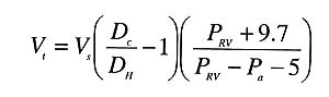
Formula 4, where:
Vt = the required minimum volume of the expansion tank (gallons)
Vs = the system volume (gallons)
PRV = the pressure at which the pressure relief valve opens (psi)
Pa = the correct air side pressure (psi)
DH = the density of the system fluid at its final (hot) temperature (lb/cubic ft.)
DC = the density of the system fluid at its initial (cold) fill temperature (lb/cubic ft).
Very Conservatively Sizing
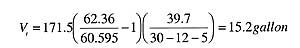
The procedure just discussed sizes the expansion tank so that system pressure is 5 psi lower than the relief valve setting when all the fluid in the system reaches the same maximum temperature simultaneously. In reality, there will never be a time when ALL the fluid in the system simultaneously reaches the maximum operating temperature. One reason is that the return side of an operating distribution system is always cooler than the supply side due to the heat being released by the heat emitters and piping. Some systems also use mixing devices to lower the water temperature supplied to some or all of the distribution system.Consider, for example, a large radiant floor heating system. Perhaps the water in the boiler reaches 180 degrees F at design load conditions. Under the same conditions, the water temperature in the distribution system is likely to be much lower. If it's a bare concrete slab, the average water temperature in the floor circuits is probably in the range of 95 degrees to 105 degrees F. Furthermore, the majority of the fluid in such a system is in the floor circuits rather than the boiler and near boiler piping.
Assume such a system has a boiler with a volume of 35 gallons, some near boiler piping with a total volume of 4.5 gallons, and 9,500 feet of 5/8" PEX tubing in the floor slab. The volume in the floor circuits is approximately 132 gallons. That's 77% of the total system volume of 171.5 gallons. Assume the proper air side pressurization is 12 psi, and the system has a 30 psi relief valve.

Modified Sizing Concept
Compare the previous example to a situation in which two hypothetical expansion tanks are sized--one for the fluid in the boiler and near boiler piping, and the other for the fluid downstream of the mixing device, as depicted in Figure 1.For the fluid volume that reaches 180 degrees F, the minimum expansion tank volume would be found as shown here:
Vt = 39.5(62.36/60.595 - 1)(39.7/30 - 12 - 5) = 3.52 gallon
For the fluid volume that reaches 110 degrees F, the minimum expansion tank volume would be found as shown in the formula at the right.
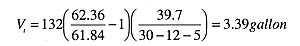
Even the modified sizing calculation is conservative in that it ignores the temperature drop of the fluid in the floor circuits and near boiler piping while the system is operating. This temperature drop tends to lower the average fluid temperature in both portions of the system, and hence, reduces the total expansion volume.

Formula 5, where:
Vt = minimum required tank volume (gallons)
Vhigh = volume of fluid contained in the higher temperature portion of the system (gallons)
Vlow = volume of fluid contained in the lower temperature portion of the system (gallons)
Dc = density of the fluid at its initial (cold) temperature (lb/ft3)
Dhigh = density of the fluid at the maximum operating temperature of the higher temperature portion of the system (lb/ft3)
Dlow = density of the fluid at the maximum operating temperature of the lower temperature portion of the system (lb/ft3)
Pair = air side pressurization of the tank found using Formula 2 (psig)
PRV = rated pressure of the system's pressure relief valve (psig)
When Does It Matter?
In smaller systems, the difference in expansion tank volume determined by these two approaches is small and the savings are probably minimal.However, things change as the size of the system increases. For example, a few years ago I helped design a radiant floor heating system containing 21 miles of 3/4" PEX tubing. The floor circuits held approximately 2,100 gallons of fluid. The boilers and near boiler piping held about 225 gallons of fluid. Ninety percent of the system's volume was in the floor circuits. Using the first procedure, the required minimum expansion tank volume would have been 223 gallons. Using the corrected procedure, the required minimum expansion tank volume was 89 gallons. The savings realized using the smaller expansion tank came to several hundred dollars.
For some jobs, the corrected calculation procedure could make the difference between an expansion tank that hangs below the air separator versus one that must be floor mounted.
Designers should also keep in mind that glycol solutions expand more than water as they change in temperature. This further increases the difference in the calculated expansion tank volumes and is especially relevant to large snowmelting systems.
Although there's technically nothing wrong with oversizing an expansion tank, it obviously adds to the installed cost of the system. Some large jobs can likely absorb this cost. One could offer the same argument for pipe sizing, closer tube spacing and oversized wiring. Good designers assess the alternatives and then decide. The design tools presented in this article can help in making that decision.
