A common method of regulating the heating or cooling output of hydronic air handlers and other types of HVAC terminal units is to vary the water flow rate through their coils. The most common flow control element is a two-way modulating valve. The valve's stem position is controlled using a pneumatic or electrical actuator that receives input from a building automation system. Feedback from a temperature sensor at the discharge of the air handler provides for closed-loop feedback control of flow.
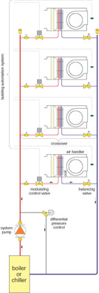
The modulating valve is customarily selected so the pressure drop through its fully open body is at least 50% of the pressure drop across the crossover piping assembly of the distribution system serving the air handler, as shown in Figure 1. This gives the valve the necessary "authority" to provide stable output control under partial load conditions.

It's common for a coil to achieve 50% of design output while operating at only about 10% of design flow. Capacity increases very rapidly at the low flow rates associated with partial load conditions. On the other hand, capacity increases very slowly as the flow rate approaches design value.
To compensate for this effect, a control valve with an equal percentage characteristic is preferred for such applications. Such valves allow flow to develop very slowly as the valve's flow control element begins to open. The farther the valve opens, the faster the flow rate increases.
The net effect of using an equal percentage valve in combination with the coil characteristic is that thermal output becomes approximately linear to valve stem position. This allows for stable control over the full travel range of the flow control element.
Although modulating valves have been used in variable flow systems for upwards of 30 years, this type of system is not without its shortcomings and complications.
Modulating valves are parasitic devices, in that they regulate flow by dissipating head energy. Ultimately, that energy is paid for as electrical energy to operate the system pump. They accomplish capacity control by "restraining" the flow that would otherwise develop through the terminal units due to the differential pressure across the piping mains.
Systems using modulating valves typically use two-pipe distribution systems that require proper balancing when commissioned. This balancing is especially important when a direct-return two-pipe vs. reverse-return two-pipe layout is used. Proper balancing requires both additional hardware and labor. In some systems, proper balancing is often never achieved, and hence the system releases too much or too little heat in some zones.
Finally, systems using modulating valves require some means of differential pressure control to avoid driving the operating point up the pump curve under partial load conditions. If this condition is not compensated for, the system could experience velocity noise, piping erosion, or capacity control problems due to valve stem lift. Differential pressure control can be done using a differential pressure bypass valve (another parasitic device that operates by dissipating pump head), or through a variable speed pump tied to a differential pressure control system.

A New Metering Device
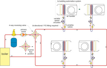
Modulating control valves aren't the only way to regulate flow through hydronic terminal units. One of the latest approaches uses small wet-rotor circulators as the "metering device." A typical layout using a one-pipe distribution system is shown in Figure 3.The small circulator associated with each air handler "shuttles" the necessary flow of heated or chilled water from a common primary loop through its associated coil. A set of closely spaced tees, or a special primary/secondary fitting such as that shown in Figure 4, provides the hydraulic separation between the primary loop and the pressure distribution developed by the variable speed circulator. This detail is vitally important to prevent the primary loop pump from inducing flow through the attached secondary circuits.
A variety of small wet-rotor circulators with power ratings as small as 1/40 horsepower are currently available to match the design load flow and head loss requirements of each secondary circuit.
Ideally, the circulator is selected with minimal extra flow/head capacity. However, if needed, a balancing valve can be installed in secondary circuits with very low flow/head requirements to ensure that the variable speed circulator is operating close to full speed at design load conditions. Purging valves should also be installed on the return side of each secondary circuit to allow bulk air removal when the system is first filled.

Primary Principals
If the secondary circuits are arranged in sequence along a common primary loop, the designer must account for the temperature drop (or temperature gain in the case of cooling) from one secondary circuit to the next. This is especially true of chilled water cooling systems operating with narrow temperature drops to ensure proper latent cooling.
With proper sizing, primary loop temperature drops of 30-40

Another way of dealing with temperature drops in a series primary loop is periodic flow reversal. Terminal units near the beginning of the primary circuit when the flow is in one direction receive the preferably high water temperatures (in heat mode). This allows for higher outputs at a given terminal unit flow rate. Upon flow reversal, just the opposite is true. In effect, periodic flow reversal allows each terminal unit to operate at the average water temperature of the primary loop. On long circuits, this can significantly decrease the overall installed coil capacity.
Periodic flow reversal should only be used when the connection between the primary and secondary loops is bi-directional (e.g., not affected by the direction of the primary loop flow). A pair of closely spaced tees does not meet this criteria, and will create a mixing effect at the primary/secondary interface when flow is reversed in the primary loop. The fitting shown in Figure 4 is bi-directional. It uses an internal baffle to minimize mixing at the primary/secondary interface.
Flow reversal can be accomplished using a single primary loop circulator in combination with a four-way reversing valve, as shown in Figure 6. It can also be done using two circulators and either a single three-way valve or two two-way valves. Although the latter two approaches are likely to have higher initial cost, they both provide a backup primary loop circulator in case one of the pumps is inoperable.
It's also possible to vary the speed of the primary loop pump based on the temperature drop of the primary loop. As the load decreases, so does the temperature drop around the primary loop. A variable speed primary loop circulator that's programmed to maintain a constant temperature drop will respond by reducing its speed and lowering electrical energy consumption under part load conditions.
Pump Parlance
The current generation of small variable speed circulators accepts a standard 2-10 volt DC or 4-20 milliamp control signal from a building automation system (or dedicated purpose controller). This is the same control signal used to operate modulating valves. A trim control on each circulator allows the starting point of the circulator to be matched to the minimum output signal of the controller.To mimic the control characteristics of modulating valves, some small variable speed circulators can be configured for equal percentage operation using an internal DIP switch. In this mode, flow rate increases slowly at low input signals and progressively faster at higher flow rates.
Many of the small variable speed circulators also come with an integral spring-loaded check valve. These valves prevent thermal migration in situations where buoyancy-induced flows would otherwise be possible.
Simplicity Achieved
Properly selected variable speed circulators operating as flow control devices reduce overall system complexity relative to modulating control valves.A distinct advantage of the primary/secondary interface is that flow in the primary loop is not affected by flow in the secondary circuits, and vice versa. This helps ensure proper flow through heat sources and chillers, regardless of the flow status in the secondary circuits. It also eliminates the need for differential pressure control in the primary loop. Good primary/secondary piping design also decreases the quantity of piping and fittings in the distribution system, thus further reducing installation cost.
Value engineering is about reducing cost without sacrificing performance. The use of small variable speed pumps as capacity control devices is certainly a good example. Get ready to see wider implementation of this new paradigm in hydronic system design.
