The control of FOG (fats, oil and grease) has long been a requirement of many industrial wastewater treatment programs at wastewater treatment plants (WWTP). The primary regulation of FOG occurs at the local level to address maintenance problems associated with sanitary blockages and accumulations of floating material in pump station wet wells and treatment tanks.
Sanitary Sewer Overflows and Grease Control
Millions of pounds of grease are generated yearly by food processing plants, cosmetic and toiletry manufacturers, food warehouses, and commercial/institutional kitchens found in hospitals, schools, prisons, casinos, grocery stores, full-service restaurants and quick-serve restaurants. This grease, if allowed to enter a wastewater collection system, can create many problems.When grease first enters the system, it is usually hot or warm. In a short period of time, it cools and coagulates on the system piping and in the lift stations. As grease solidifies on the interiors of pipes, sewerage flow becomes restricted. Grease buildup in the sewers causes capacity problems and blockages. Lift station pumps and sensors can be fouled by grease and malfunction.
The U.S. Environmental Protection Agency (EPA) requires municipal sewer authorities to implement pretreatment or "source control"
Design of GRDs
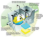
Although the design of the original grease-removal device (called the Diskimmer) has changed little in its 29 years of commercial use, the modern automatic electrical/mechanical GRD as a whole has seen some important changes, mostly involving vessel design and construction. The first grease-removal units were manufactured of carbon steel. Most manufacturers changed to stainless steel due to the corrosive nature of the acidic grease-laden wastewater originating from the kitchens. Trash screens have been added to remove solid food and waste products.Testing and calculations have proven that longer, larger-capacity units increase the retention time and offer improved performance. The design must follow the basic principles governing separation of grease from water by gravity differential. The expressions involved, their relationship to the system's design, and their derivation are all an expression of Stokes' Law for terminal velocity of spheres in a liquid medium, which is applicable to the rate of rise of grease globules, or the rate of settling of solids, in water.
The formula for Stokes' Law is: Vt = g (sw-sg) D2/18m
Where:
Vt = rising velocity of the grease globule in cm/sec
g = gravity constant (980 cm/sec2)
m = viscosity of water in poises (0.01)
sw = densities (gm/cm3) or specific gravity of water
so = densities (gm/cm3) or specific gravity of grease
D = diameter of the grease globule in cm
An examination of Stokes' Law discloses that the vertical velocity of a grease globule in water depends on the density and diameter of the globule, the density and viscosity of the water, and the temperature. Specifically:
- The grease globules' vertical velocity is highly dependent on their diameter, with small globules rising much more slowly than larger ones. The larger the globule, the faster the rate of separation.
- The performance of the system will be highly dependent on the difference between the specific gravity of the water and that of the grease. The closer the specific gravity of grease is to that of the water, the slower the globules will rise; the greater the density difference between the grease and water, the faster the rate of separation.
- Since the grease globules' rise rate is inversely proportional to the viscosity of the wastewater, the less viscous the carrier fluid, the faster the rate of separation and vice versa. Grease globules will rise more slowly at lower temperatures and more rapidly at higher temperatures. Grease, especially when hot or warm, is lighter than water and will not mix well with water.
Another critical factor in removing FOG from the incoming wastewater stream is retention time, which is the theoretical time that the water is held in the grease removal device tank. The volume of the tank for the required retention time can be computed as follows:
V = QT
Where:
V = volume of the grease removal device tank (gal)
Q = rate of flow (gal/min)
T = retention time (min)
The retention time, unless otherwise indicated, is based on the full systems rated flow. The wastewater entering the grease-removal device tank requires a certain amount of time for gravity separation of the FOG to occur. Therefore, designing to the proper retention time is an important factor in determining the effectiveness of the device.
Unit retention time plus required effluent discharge limits are the prime factors in sizing.
Specifying Applications
Automatic electric/mechanical GRDs are used in facilities where prepared food is sold and in many other types of food establishments in which any food preparation (including heating or defrosting in or by means of any kind of oven or heating device) takes place on the premises.Grease discharges are predominantly generated from washing and cleaning operations in these facilities. The pot-washing sink, pre-rinse station (prior to the dishwasher), floor drains, and automatic and manual ventilation hoods are the major sources of grease discharge to the sewer system.
The plumbing engineer or Authority Having Jurisdiction (AHJ) may specify automatic electrical/mechanical GRDs either as a "point-source"
Sizing of GRDs
The automatic GRD is generally sized according to local plumbing codes and should be sized to handle the amount of wastewater and grease that will flow to it. A check of local ordinances and codes should always be made before the system is designed. As grease is constantly removed, the sizing is based primarily on the volume of wastewater in gallons per minute that can be discharged from kitchen fixtures and equipment to be served. Because sizing is based on hydraulic loading, it can be calculated from the number and kind of sinks and fixtures discharging to the system. Most plumbing codes list drainage fixture-unit values for various plumbing fixtures. For fixtures not listed, these codes usually show drainage fixture-unit values based on the drain outlet diameter.
When a food-service facility is remodeling, or when the facility has been cited for a grease discharge by the AHJ and is required to install a new automatic GRD, the plumbing engineer must determine the equipment size and establish how often the grease must be removed. A flow test can be performed by the plumbing engineer on the existing facility's drainage system to determine minimum, average, and maximum discharge flow. A flow test is one of the most reliable methods for determining the proper sizing for an automatic GRD or any treatment equipment.