
Issue: 7/02
Whether it is business, industry, education or the popular television program, policies and programs are only as effective as the weakest link. Plumbing and mechanical professionals need to appreciate the significance of this axiom, especially when it involves a steam system. Just one weak (steam system) link can be embarrassing, sometimes costly and potentially dangerous.
The weakest link when it comes to steam systems may not be an individual component, but a fundamental lack of knowledge. For example, a steam trap, when properly installed, may be the most beneficial but least understood piece of equipment in the system. However, the lack of knowledge about steam traps and how they function can result in excessive energy loss, compounded environmental costs, productivity problems, and yes, safety concerns for personnel and property.
Higher education seldom offers courses covering a comprehensive overview of steam traps. Therefore, plumbing and mechanical engineers and professionals are left to fend for themselves and to ferret out useful information. This article is intended to help systems designers better understand and appreciate the complexities of selecting and specifying the right type of steam trap for specific applications.
Trap Basics
A steam trap is an automatic valve designed to remove condensate, air, and CO2 from the steam system. The trap opens automatically to discharge condensate and closes to prevent steam loss from the system.Over the years, a number of types of steam traps have been marketed. Although they vary in design, they all use one or more of the three basic operating principles relating to density, temperature, or velocity. Four types of steam traps have emerged which presently fill most industrial and process requirements. The types are: inverted bucket, thermostatic, float and thermostatic, and controlled disc.
What is the best type of trap to use? Careful, it's a "trick question" that will get one "discharged" from the TV series.
The correct answer is, "It depends." It depends on the application and the operating requirements. It also may depend on what the user expects from the steam trap. Based on feedback information from several hundred trap users, the following list represents the most frequently mentioned trap expectations:
- Traps must minimize steam loss.
- They must operate trouble-free with minimal adjustments or maintenance.
- They must deliver maximum efficiency of the heat exchange equipment being trapped.
- They are expected to have a long operating, or service life.
- They must operate with maximum safety.
- They must be highly reliable, even under dirty steam conditions.
These expectations can be met only with a properly specified, installed and maintained steam trap. A misapplied steam trap can lead to premature failure, and a steam trap that allows live steam to pass through an open orifice is extremely wasteful.
Consider this: a steam trap with a 5/16" orifice blowing steam will cost approximately $19,500 each year (Table 1). If there are just five traps this size wasting steam, the loss is more than $97,000 a year.
Table 1. Cost of Various Sized Steam Leaks at 100 psi
Size of Orifice (in) Lbs. Steam Wasted Per Month Total Cost Per Month Total Cost Per Year 1/2 835,000 $4,175.00 $50,100.00
7/16 637,000 3,185.00 38,220.00
3/8 470,000 2,350.00 28,200.00
5/16 325,000 1,625.00 19,500.00
1/4 210,000 1,050.00 12,600.00
3/16 117,000 585.00 7,020.00
1/8 52,500 262.50 3,150.00
In addition, with every pound of steam loss, there is a corresponding increase in pollution (carbon monoxide [CO], nitrogen oxides [NOx], particulate matter [PM], sulfur oxides [SOx], and other compounds) created when fossil fuel is burned to generate replacement steam.
Understanding How Traps Operate
Those who engineer steam systems and specify steam traps need to understand the difference among the types before determining the best trap for an application. Using the following information will help one decide whether to specify an inverted bucket, a thermostatic, a float and thermostatic, or a thermodynamic (disc) trap in a given application.
Inverted Bucket Traps
As the name implies, these traps use an upside-down bucket that is normally submerged and floats only when steam is present. The bucket sinks when the volume of condensate exceeds a predetermined liquid level. When the bucket sinks, the valve at the top of the trap opens (Figure 1).Condensate enters the trap and flows under the bottom of the bucket to fill the trap body. The bucket remains completely submerged, and condensate discharges through the valve at the top.
When steam enters the trap, it too collects under the bucket, causing it to become buoyant. Buoyancy causes the bucket to rise, thus closing the valve by returning it to the seat. Air and CO2 pass through a vent in the top of the bucket continuously and collect at the top of the trap. Condensate continually drains into the trap.
When sufficient condensate collects under the bucket to displace the steam inside that bucket, the bucket buoyancy will be lost, causing it to sink. As the bucket sinks, its weight will pull the valve away from its seat. Once the valve is open, accumulated air and non-condensables are forcibly discharged, followed by condensate. After the condensate has been discharged, steam again enters the trap and floats the bucket, thus the cycle starts over.
Inverted bucket traps are rated for pressures from 0 to 2,500 psig and higher, and are fabricated in a variety of materials, including cast iron, stainless steel, carbon steel, and alloy steel.
Thermic bucket traps that permit quick venting of start-up air can be provided. However, if large volumes of air must be vented at or near steam temperature, the bucket vent can be enlarged or a bellows-type thermostatic air vent can be installed above the inverted bucket trap and in parallel with it. Inverted bucket traps installed with a simple pressure sensitive draining device drain free of condensate when steam has been shut off.
Inverted bucket traps effectively handle dirt and scale because the valve is located at the top. Small particles are not permitted to accumulate, but are discharged immediately with the condensate as a result of the strong scrubbing action of the intermittent discharge. Particles too large to be "scrubbed out" fall into the bottom of the trap away from the valve and seat. Because the float (inverted bucket) is open, the trap is not damaged by water hammer.
An inverted bucket trap functions as long as the differential pressure is positive. Although it reduces trap capacity, back-pressure of up to 99% does not cause the trap to blow open and waste energy. This feature is critical, especially when multiple traps discharge into manifolds.
Because the inverted bucket trap has the longest service life of any type of steam trap, it is the most efficient in terms of energy conservation and should be installed where reliability and service life are important.

Thermostatic Traps
Thermostatic traps operate on the temperature difference between steam and cooled condensate and air. On start-up, condensate and air are pushed ahead of the steam directly through the trap. Inside the trap is a temperature-sensitive element. This element may be bimetallic, but is most often a sealed bellows partially filled with a liquid, such as distilled water. The liquid-filled bellows is normally contracted, leaving the valve open (Figure 2).As steam enters the trap body, the temperature inside the trap increases quickly and heats the liquid-filled bellows. As the liquid "boils," vapor pressure inside the bellows increases. When pressure inside the element becomes balanced with the steam pressure in the trap body, the spring effect of the bellows causes the element to expand, closing the valve. As the temperature in the trap drops a few degrees below saturated steam temperature, condensate begins to back up inside the trap. The imbalanced pressure contracts the bellows, thus opening the valve.
The amount of condensate backed up ahead of the trap depends on the load conditions, steam pressure and piping. It's important to note that because thermostatic traps close in the presence of condensate near steam temperature, they also can back up air and other non-condensables, such as oxygen and CO2.
Movement of the trap valve is also caused by changes in the temperatures of steam and condensate flowing through the trap. When the temperature differential between condensate and steam is small, vapor pressure inside the bellows causes expansion to tightly close the valve.
Industrial thermostatic steam traps are normally rated to operate on pressures from 0 to 300 psig and are fabricated with stainless steel, carbon steel, and cast iron housings. Thermostatic steam traps can be used very successfully for venting air from a steam system when the installation is in addition to, and mounted above, a condensate trap. When air collects, the temperature drops and the thermostatic air vent automatically discharges the air at slightly below steam temperature at all operating pressures from 0 to 300 psig.
A thermostatic trap is not particularly effective when dirt and scale are present. In addition, the bellows may be damaged by relatively mild water hammer. A cooling leg of insufficient length results in condensate backing up in steam lines or heat exchange equipment, causing corrosion in pipes and coils, and possible freeze damage or water hammer. Whether used as a condensate trap or as an air vent, thermostatic steam traps should be inspected and maintained frequently to prevent energy loss and reduced efficiency.
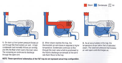
Float and Thermostatic Traps
This type of steam trap combines the actions of two principles: thermostatic and density. The trap's operation is relatively simple. A valve with a ball float actuator drains condensate when the liquid reaches a predetermined level in the trap. When the flow of condensate diminishes, the float drops, partially closing the valve to accommodate the flow rate (Figure 3).At the top of the trap is a thermostatic element (similar to that used in a thermostatic trap) that opens to discharge all air and non-condensable gases as soon as they cause a small temperature drop within the trap. The float and thermostatic trap is normally rated to operate on pressures from 0 to 250 psig and higher. They are usually made of cast iron or steel.
Float and thermostatic traps are particularly well suited when the system being drained operates on a modulating steam pressure and when the air, water, or product is heated to a temperature below 212 degrees F. Under these conditions, pressure in the heat exchanger may vary from the maximum steam supply pressure to vacuum. For the trap to drain properly, vacuum breakers must be installed. Subsequent venting of the air introduced by the vacuum breaker when higher steam temperatures are demanded requires a separate air-venting orifice. Float and thermostatic traps provide excellent service during start-up and on very light loads, and operate efficiently against back-pressure.
The condensate valve in this type of trap is located at the bottom and is subject to plugging when dirt and scale are present. Therefore, a strainer should be used to protect the trap. Strainers must be regularly maintained--a plugged strainer is worse than none at all. If dirt particles prevent the valve from closing, steam energy is wasted until the condition is detected and corrected. A consideration in the selection of a float and thermostatic trap is that the closed float and bellows elements within the trap are highly susceptible to water hammer damage.

Disc Traps
Disc traps are small and lightweight, and therefore, easy to install, but their operating characteristics should also be considered. Under normal operating conditions, disc traps operate as a function of velocity. Condensate and air enter the trap and pass through an inlet orifice, a control chamber, and in some designs, an insulating chamber. This chamber is designed to isolate the trap against the effects of the environment (Figure 4).The impact of condensate lifts the disc off the inlet orifice, allowing condensate to flow through the outlet passage. When steam reaches the inlet orifice, it flows at a higher velocity than the condensate, and thus the pressure between the disc and the seating surfaces is reduced. The disc is driven against the seat because of pressure loss between disc and seat, shutting off the flow. It is held on the seat as long as the pressure times the area above the disc (closing force) are greater than the sum of the inlet and back pressure times their respective acting areas (opening force). Controlled bleeding of steam, condensing in the control chamber, or both, reduces the pressure above the disc, permitting the trap to open and discharge condensate.
The trap re-closes as condensate near steam temperature enters the inlet orifice. Flashing condensate can close this trap, preventing the removal of non-condensable gases. Some disc traps incorporate an optional strainer screen to prevent dirt from plugging the orifice or otherwise causing malfunction of the close tolerance parts.
Disc traps are normally rated to operate on pressures from 10 to 600 psig and are fabricated of carbon steel or stainless steel housings with stainless steel components to resist corrosion.
Disc traps drain free, preventing damage from freezing; if they are piped with the disc in the vertical plane, a vacuum breaker is used, and a discharge to an open drain is provided. Closed return systems subject to pressure build-up can prevent drainage of any trap.
Because of their operating principle, disc traps are susceptible to blow-through failure when back-pressure is high (>50% of inlet). This characteristic is especially important now because of the trend toward installation of traps that discharge into a return header rather than to atmosphere.
A bank of steam traps blowing open raises the pressure in the condensate return lines. This condition may cause thermal shock and prevent condensate drainage from equipment on modulating pressure steam supply systems. Although easy to install, disc traps are not energy efficient because of their short service life. They should be installed only where they can be inspected frequently, and repaired or replaced as needed.
Before You Specify
No single type of trap is ideal for every application. One trap may be the easiest to install, another the most effective in handling air, and yet another the most effective in minimizing energy loss. Table 2 summarizes how various traps perform in meeting specific operating requirements. The table shows how each type of trap measures up to expectations based on the characteristics in the left column.
Table 2. HOW STEAM TRAPS MEET OPERATING REQUIREMENTS.
Characteristic Inverted Bucket F&T Disc Thermostatic
Method of Operation (1) Intermittent Continuous Intermittent (2) Intermittent
Energy Conservation (Time in Service) Excellent Good Poor Fair
Resistance to Wear Excellent Good Poor Fair
Corrosion Resistance Excellent Good Excellent Good
Resistance to Hydraulic Shock Excellent Poor Excellent (3) Poor
Vents Air and CO2 at Steam Temperature Yes No No No
Ability to Vent Air at Very Low Pressure (1/4 psig) Poor Excellent (4) NR Good
Ability to Handle Start-up Air Loads Fair Excellent Poor Excellent
Operation Against Back-Pressure Excellent Excellent Poor Excellent
Resistance to Damage from Freezing (5) Good Poor Good Good
Ability to Purge System Excellent Fair Excellent Good
Performance on Very Light Loads Excellent Excellent Poor Excellent
Responsiveness to Slugs of Condensate Immediate Immediate Delayed Delayed
Ability to Handle Dirt Excellent Poor Poor Fair
Comparative Physical Size (6) Large Large Small Small
Ability to Handle "Flash Steam" Fair Poor Poor Poor
Mechanical Failure (Open-Closed) Open Closed (7) Open (8) Open/Closed
1. Drainage of condensate is continuous. Discharge is intermittent.
2. Can be continuous on low load.
3. Bimetallic and wafer traps--good.
4. Not recommended for low pressure operations.
5. Cast iron traps not recommended.
6. In welded stainless steel construction--medium.
7. Can fail closed due to dirt.
8. Can fail either open or closed depending upon the design of the bellows.
Remember, this table is only a tool to understanding how various types of steam traps respond to some operational characteristics. More important than an individual characteristic is the actual application in which the steam trap will be used.
Conclusion
A fundamental lack of knowledge has caused more than a few contestants to be voted off the "Weakest Link" television series by their associates. To survive the weakest link "honor" in business and industry, individuals who consult with owners and designers of steam systems, or those who specify steam system components, must become fully informed about steam traps and how they operate under specific conditions.Lessons to be learned for overcoming the fundamental lack of knowledge boil down to three main points: 1) Understanding the operational characteristics of each type of steam trap; 2) specifying the right type (model and size) of trap for the given application; and 3) installing and maintaining the traps according to the manufacturer's recommendations.
It's essential for all responsible parties to have a working understanding of how and why steam traps operate. With a solid foundation of knowledge, they will now understand why failure to properly specify, install and maintain steam traps will impact the system's performance and functionality. Having read this far, you should have no problem moving on to the next higher round of competition in the game category of steam energy economics.


