Pssst! You there, brazing that 1-inch copper tube! Wanna cut your brazing time in half and improve the quality and reliability of that joint? You can, but first you need to set aside some "conventional wisdom"
Cup Depth
The first conventional wisdom to set aside is that the fitting you are using is suitable for brazing. If it's a standard copper fitting that you bought at the local plumbing supply house, it's designed for soldering, not brazing. How can you tell? If the cup depth is about two-thirds of the socket diameter, the fitting is suitable for soldering and not brazing. What would make the fitting suitable for brazing? A much shallower cup.The dimensions of solder-joint fittings were established around 1950 based on testing that was performed by the National Bureau of Standards (NBS). NBS discovered that solder1 was not very strong and that plenty of overlap (i.e., socket depth) was needed to ensure that soldered joints did not come apart in service.
In comparison, brazing filler metals2 (e.g., BCuP and BAg types) are 7 to 10 times stronger than solder, so brazed joint overlap does not need to be as long as soldered joint overlap. This fact was established in the late 1950s when over 1,200 test specimens were brazed in a round-robin series of tests performed by 10 labs using various materials and overlaps. The results were published as American Welding Society Standard C3.1-63. In brief summary, the testing showed that an overlap equal to two times the thickness of the thinner member (2t) is all that is required to develop brazed joint strength equal to the tube strength.

More Insertion Is Not Better
The second bit of conventional wisdom to set aside is that more insertion means a better joint. This is wrong. Excessive overlap makes the joint harder to make well and less likely to perform well in service.A copper-brazed joint with long overlap will be softer than one with less overlap because the extra heating time needed when the overlap is longer results in more annealing of the copper, making it softer. Although excessive softening will not result in bursting of the tube in service, softened joints will bend easily, making it difficult to install the tubing with uniform pitch and alignment.
Longer brazing times also result in more oxidation of the copper. Excessive brazing time will result in scaling of the inside of the tube, which can contaminate the product stream and plug up control devices. Keeping brazing time short minimizes this risk.
Recent publications by the Copper Development Association (CDA) and the Air-conditioning and Refrigeration Institute (ARI) have shown that excessive overlap is a major contributor to joint failure. Because excessive overlap makes it more difficult to heat the joint properly, many joints have large voids that cause failure within a couple of years, especially when vibration is present. (See www.brazingdimpler.com for copies of the pertinent research papers.)
Long Overlap Makes a Poor Joint
The third bit of bad conventional wisdom is that it should not make any difference to the brazer if the overlap is long or short if the brazer is competent and qualified. The fact is that the difficulty in making a brazed joint increases dramatically as the overlap increases. Qualification codes such as ASME Section IX and AWS B2.2 recognize this indirectly by limiting the overlap that a brazer may use in production to 1.25 times the overlap he used on his test piece. But ultimately, nobody checks brazed joints to see how sound they are before they are put in service. The only test is long-term service history, and the ARI data says that $30 to $90 million of rework is needed due to poor brazed joint quality.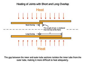
- 1) The longer the overlap is, the further the braze metal has to flow, and the more opportunity there is to trap gas, which causes voids in the joint. Further, as the diameter becomes larger, the overlap increases, and proper heating of the joint becomes progressively more difficult because more of the tube is protected from the heat of the flame (see Figure 1).
- Buy braze-joint fittings. Unfortunately, they are not readily available commercially and cost six to eight times what solder joint fittings cost.
- Have a machine shop trim off the excess cup material. This works, but it is quite expensive.
- Have the brazer trim off the excess cup material in the field. This is also expensive, and will result in distorted fittings and bad fit-up, leading to poor quality joints.
- Fit the pipe into the tube with only a short overlap. Although this works, it is very difficult to control since the tube is free to move in and out of the fitting during brazing.
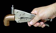
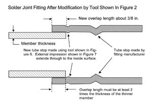
- Deform the fitting near the end using a specialized tool. This simple hand tool limits the depth of insertion and provides a positive tube stop (see Figures 2 and 3).
- It is not necessary to insert copper pipe completely into a solder-joint socket to develop full strength in the joint when brazing. A depth of insertion equal to twice the thickness of the thinner member will develop a joint that is stronger than the base metal with all brazing filler metals that are commonly used on copper.
- Depth of insertion greater than 2t adds nothing to the strength of the joint.
- Depth of insertion greater than 2t increases annealing time, which softens the base metal and can lead to scaling of the tube inner wall.
- Excessive overlap only makes brazing more difficult for the brazer, increases the presence of voids and reduces service performance of the joint.
- Practically speaking, one can use braze-joint fittings with full insertion, solder-joint fittings with partial (but adequate) insertion, and solder-joint fittings with cups that have been shortened but still have adequate socket depth.
- Reducing the joint depth reduces the time needed to properly heat and complete the joint by 50% or more, improves the service performance of the joint and reduces the amount of brazing filler metal used.
Footnotes
1 Solders typically melt at around 400
2) When brazing filler metal begins to melt, it becomes a two-phase mixture (i.e., a slush) until it reaches about 300
If excessive overlap offers no advantage and many disadvantages, what can a brazer do to reduce the overlap, lower installation cost, improve joint quality and make the brazer's life easier?
Cost Reductions When Using Shorter Overlap
The fourth bit of faulty conventional wisdom is that it's not worth the trouble to do any of the above.Reducing the overlap to approximately 3/8-inch for all tube sizes reduces the filler metal consumption by 50% to 75%. The savings can be significant on a job where silver-containing filler metals are used (see Table 1).
Most significantly, reducing the overlap to 3/8-inch reduces the time required to braze a joint. Experience shows that the time required to braze a 1-inch joint is reduced by 50%, and even more time is saved for larger joints. For joints in excess of two inches, the shallow cup is also easier to assemble, reducing brazing time even further.
Conclusions
Several conclusions can be drawn from this information:
