Issue: 1/04
Over the past years, I've written many articles on hydronic heating for PM Engineer. Most have been aimed at engineers who've been designing hydronic systems for some time and want to hone their designs to take advantage of new techniques or hardware.
Given the growth of the hydronics industry, young mechanical engineers just starting out at consulting firms will be expected to quickly learn the basics of hydronic system design. Many will have little more than one undergraduate course in fluid mechanics, thermodynamics and heat transfer. Although such courses do present theory applicable to all hydronic systems (Bernoulli's principle, the Darcy-Weisbach equation, etc.), many engineers just entering the field find it difficult converting such theory into the nuts and bolts of a modern hydronic system.
I know this from personal experience. As an aerospace engineering major at a major technical university I was inundated with courses in fluid mechanics, heat transfer, thermodynamics and control theory. Not once did my professors discuss circulator sizing, primary secondary piping or how to protect a boiler from flue gas condensation. By graduation, I could calculate the shock wave angle for a nose cone mounted in a hypersonic wind tunnel, but not the pressure drop of water flowing at 10 gpm through a one-inch globe valve. The lack of discussion on such "mundane"
Establish a Target Flow Rate
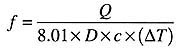
The first step in selecting a tube size is to estimate the flow needed to carry heat to a load at a specified rate. I call this the "target"

Where:
c = specific heat of water (Btu/lb/°F)
D = density of water (lb/ft3)
T = water temperature (°F)
Assume, for example, that you're trying to size a tube to carry 100,000 Btu/hr to a load. The supply temperature will be 180°F, and you select a design temperature drop of 20°F. The flow rate of water required for these conditions is found in the equation at the right. Although it is "customary"
Determine the Tube Size
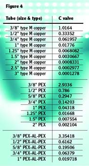
Once the target flow rate has been calculated, tube size can be selected based on flow velocity limitations. A practical approach is to select a size that keeps the flow velocity in the tube in the range of two to four feet/second. The lower end of this range provides sufficient velocity to entrain air bubbles and carry them along until the flow passes through an air separator. Flow velocities lower than two feet/second may not entrain larger air bubbles, especially in downward flow through a vertical pipe. The upper end of the velocity range keeps flow noise at acceptable levels for tubing passing through, above, or below occupied space.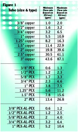
When the flow rate falls within the range of two tube sizes, the larger size always provides the lowest operating noise as well as the lowest head loss.
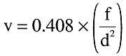
Equation 4
Where:
v = flow velocity (feet/second)
f = flow rate (gpm)
d = exact inside diameter of pipe (inches)

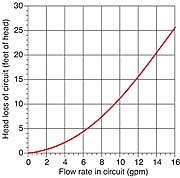
Determine the Circuit's Head Loss
In preparation for selecting a circulator, you also need to know the head loss of the proposed piping circuit at the estimated operating flow rate.
In the context of closed loop hydronic systems, "head"
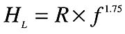
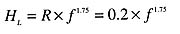
Equation 5
Where:
HL = head loss of circuit (feet of head)
R = hydraulic resistance of piping circuit
f = flow rate (U.S. gpm)
1.75 = the exponent of the flow rate


In part two of this series we'll use the system curve and target flow rate to select a circulator.
In the meantime, you may want to set up a spreadsheet to calculate the various fluid properties and other parameters we've discussed. You'll need to calculate them many times as you hone your hydronic design skills.
