Editor's Note: "Back to Basics" is a column that will run periodically in PME reviewing the basic principles of plumbing engineering.
Most professionals with a strong plumbing background are pretty confident about the wet side of a boiler installation. But, it is just as important to fully understand the importance of venting combustion by-products outdoors. Ensuring that flue products are properly and safely removed from a boiler and carried outside of a building is essential to ensure proper boiler operation.
Venting Systems
Vent systems operate as basic negative draft systems or as positive pressure flues, or with a fan-assisted vent system. The easiest way to determine the type of vent system required on your boiler is to consult the manufacturer's installation instructions supplied with the boiler. The venting section of the instructions should offer clear guidelines for proper vent system installation. These requirements are also noted on the boiler's rating plate, which is affixed to each unit. The rating plate contains basic information about the boiler, such as the manufacturer, model number, input and the vent category. All gas-fired, low pressure steam and hot water boilers certified to the ANSI Z21.13 standard are required to have the vent system category (I, II, III or IV) on the rating plate.
The ANSI Z21.13 standard contains a uniform test procedure used to evaluate the vent system of all certified boilers. Vent category specifies whether the vent system operates under a negative pressure or a positive pressure, and if it is possible for the products of combustion to condense into a liquid in the flue. The ANSI Z21.13 standard vent category test measures carbon dioxide concentration and the net temperature of the flue gases to determine if condensate formation is likely in the vent system. This test is very similar to the combustion efficiency measurement that can be taken in the field during a boiler start-up. As the efficiency of a boiler goes up, the temperature of the flue gases go down, and the gases are more likely to condense in the flue. When combustion efficiency exceeds approximately 83%, there is a good possibility that the flue products will condense.
It is essential to understand what the vent category means in order to select correct venting materials and properly terminate the flue.
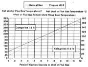
With the permission of the Canadian Standards Association, Figure 1 is reproduced from ANSI Z212.13-2000/CSA 4.9-2000, which is copyrighted by Canadian Standards Association, 178 Rexdale Blvd., Toronto, ON M9W 1R3, www.csa.ca. While use of this material has been authorized, CSA shall not be responsible for the manner in which the information is presented, nor for any interpretations thereof. For more information on CSA America or to purchase standards, please visit www.csa-america.org or call 1-800-463-6727.
Category I
A Category I vent system is the most common vent category (Figure 1). This vent system operates with a negative draft, and the products of combustion are hot enough to stay well above dew point. (Dew point is the temperature where the gaseous products of combustion condense into a liquid.) Since a major portion of gas flue products is water vapor, condensing can occur when the flue products are allowed to cool below dew point. This is especially problematic to the vent system, because of acidic condensate. When the vent layout and materials are not designed to withstand this acidic condensate, rapid damage to the vent system can occur and impede proper operation of the boiler.
Negative pressure in a Category I vent system is generated by the buoyancy of the heated flue products. The elevated temperature of the flue gases makes them less dense than surrounding air, so the heated flue products rise. A Category I vent system is typically vented with Type "B" vent materials.
Category II
A Category II vent system also operates with a negative pressure in the vent, but the temperature of the flue products has cooled to a point where they may condense into a liquid in the flue. A Category II vent operates with a negative pressure, so all design considerations of a Category I vent system must be considered in addition to condensate formation. A Category II vent requires vent materials that are resistant to the corrosive effects of flue gas condensate.
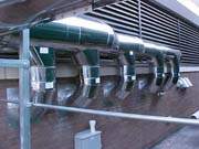
Five Lochinvar Power-Fin, 2,000,000 Btu/hr boilers are common vented at the Auto Owners Insurance Headquarters in Lansing, MI, with AL29-4C, Category IV vent material. (Installed with a modulating draft vent system.)
Category III and IV
Category III and IV vent systems operate with a positive pressure in the vent system. This positive pressure in the vent system is generated by a power exhauster operating the combustion process and/or the vent process. Positive pressure vents must be fully sealed to prevent spillage of flue products into an occupied portion of the building. Category III and IV vent systems are also evaluated to determine if they are likely to condense in the flue. A Category III vent system maintains flue gas temperatures above dew point and should not condense in the flue. A Category IV vent system's flue products cool below their dew point, therefore it is possible they may condense in the flue.
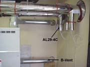
Lochinvar Energyrite2(R), Pool Heater drawing combustion air in through a side wall with Category I B-Vent material and exhausting flu products with Category IV vent material, AL29-4C.
Specialized Vent Systems
In addition to the four vent categories, many boiler manufacturers offer specialized vent systems. These are typically direct vent systems utilizing some form of a two-pipe system. In a two-pipe system, one pipe vents the products of combustion outside the building while the second pipe draws combustion air from outdoors. These direct vent systems are not categorized by the ANSI Z21.13 test standard, but they are performance tested within installation limits set by the boiler manufacturer. The boiler manufacturer must provide either complete specification for the required vent materials and terminations, or supply specific vent material for specialized vent systems.
These optional venting systems can add a great deal of installation flexibility. Any additional cost in vent materials and components are often offset due to the unique qualities of a direct vent system, which allows longer than normal horizontal vent runs and side-wall terminations. In addition, the separate pipe for combustion air sent directly to the boiler removes the need to install expensive combustion air louvers and space heaters in the equipment room.
Vent Material Selection & Sizing
Material selection and sizing for the vent system of a Category II, III or IV boiler is determined by the information contained in the manufacturer's installation instructions, which is based on performance testing under the requirements of the ANSI standard.
Choosing the proper material for vent systems is essential for vent system safety. A Category I vent should be vented with Type "B" double wall vent materials. The double wall vent pipe provides an insulating air space between the inner pipe, carrying the flue products, and the outer pipe, which is exposed to the ambient temperatures in the equipment room. This double wall vent pipe retards heat loss and helps to ensure that the temperature of the flue products is maintained to generate the necessary negative draft in the flue. Single wall vent pipe may allow excessive radiant heat loss and could result in a loss or reduction in draft. This could cause flue gas spillage or condensation, resulting in hazardous operating conditions. Most manufacturers of high efficiency products, conforming to the ASHRAE minimum standards, require installation of double wall vent. Some manufacturers allow the installation of a single wall vent with an insulation wrap on the outside of the vent. Check with the manufacturer and local codes before using this as an alternate to the Type "B" vent materials.
All vent systems other than Category I must use Category IV vent materials, which are typically more expensive. Category IV vent materials are typically fully sealed and constructed from an AL29-4C stainless steel to withstand the possible corrosive effects from acidic flue gas condensate.
The first step in sizing a Category I vent system is to determine the required vent size. The minimum vent diameter suitable for the installation of any boiler is the flue outlet diameter of the boiler. Never decrease the diameter of the installed vent system smaller than the boiler's flue connection point for a Category I boiler. After reviewing the parameters of the proposed vent system, you may find that the installed vent needs to be larger than the outlet provided on the boiler.
Next, determine what type of combustion system is used on the boiler. An atmospheric combustion system will typically have a larger volume of flue products moving up the flue because of the secondary air that is involved in the combustion process and the larger volume of dilution air added by a draft hood. Therefore, the vent diameters of an atmospheric boiler are larger when compared to a fan-assisted combustion boiler. A fan-assisted combustion boiler typically uses a mechanical fan to operate the combustion process at a relatively low pressure (usually measured in inches of water column pressure). This pressure dissipates as the products of combustion exit the flue opening of the boiler. The flue products then rise due to their natural buoyancy and generate a negative draft. Almost all of the air supplied to fan-assisted combustion systems is primary air, with very little secondary air. This means that the total volume of flue products per Btu of input is reduced when compared to an atmospheric combustion boiler.
In addition, dilution air to the Category I vent system may not be required or, if required, is supplied by a barometric damper. A barometric damper provides significantly less dilution air than an average draft hood, further reducing the total volume of flue products from a fan-assisted boiler.
Vent System Configuration & Installation
How high will the vent system rise vertically? How long is the horizontal run of the vent pipe? How many elbows are required? Once you have gathered this information, consult the basic guide to properly install a Category I vent system. This guide is The National Fuel Gas Code (NFGC), also known as ANSI Z223.1 or NFPA 54, which sets forth basic venting requirements for all natural draft Category I gas-fired appliances.
The NFGC is the basis for most local venting codes, as well as the venting requirements contained in the boiler manufacturer's installation instructions. The NFGC contains all cautions and guides for vent system installation and termination. In addition, the NFGC contains a series of tables that give the Btu/hr capacity of various vent pipe diameters based on the horizontal run length and vertical height of the vent system. The vent tables contain two columns. The combustion system (atmospheric or fan-assisted) utilized by your boiler will determine the column you will select to size the vent system. The NAT (atmospheric combustion boilers) column has a single maximum Btu/hr capacity for the selected vent diameter at various lengths of vertical and horizontal vent pipe. The FAN (fan-assisted combustion boilers) column contains a minimum and a maximum Btu/hr capacity listed for each corresponding diameter of vent pipe.
Many fan-assisted boilers stage-fire or modulate to lower inputs. Ensure that this reduced boiler input meets the minimum input requirement for the selected vent diameter. It is important to note that the Btu/hr capacities shown in the venting tables assume that the typical venting system contains two 90-degree elbows or four 45-degree elbows. Deduct 10% from the Btu/hr capacity of the vent for each additional 90-degree elbow.
A Category I vent system works by allowing heated flue products to rise vertically, so the vent pipe must rise vertically from the boiler vent connection as soon as possible. You should also limit the length of the horizontal flue pipe. All horizontal runs of vent pipe must rise 1/4 inch per foot of run to maintain proper draft in the vent. Any time the horizontal run of a vent is more than 1-1/2 feet for each inch of vent diameter, it is possible that you will have trouble generating the necessary draft for proper operation. The longer the horizontal run, as compared to the vertical rise, the more likely you are to have problems with the vent system.
In addition to the vent tables for single appliance installations, the NFGC contains tables for combined venting of multiple Category I appliances. These tables contain information for sizing vent connectors as well as the common vent diameter. The common vent tables have columns based on whether you are combining multiple fan-assisted units (FAN+FAN), multiple fan-assisted and atmospheric units (FAN+NAT), or multiple atmospheric units (NAT+NAT).
The NFGC also contains basic requirements for the location of the vent termination point. These requirements address the clearances required for installation on flat roofs with parapet walls and pitched roofs. Following these basic clearance requirements can help to prevent problems caused by prevailing winds at rooftop terminations.
Proper venting of combustion products to the outdoors is essential for the safe operation of a gas-fired boiler. The complete National Fuel Gas Code is available from the National Fire Protection Association through its Web site at www.nfpa.org, or by calling 1-800-344-3555. In addition, several venting material manufacturers provide vent sizing and application guides that contain venting tables and vent installation guidelines from the NFGC. The venting manufacturers' guides provide an excellent reference for venting installation at little to no cost.