Editor's Note: "Back to Basics" is a new column that will run periodically in PME reviewing the basic principles of plumbing engineering.
A sanitary drainage system is a system of piping within public or private premises that conveys sewage or other liquid waste to an approved point of disposal. The intent is to design and install sanitary drainage systems that will function reliably, are neither undersized nor oversized, and are constructed from materials, fittings and connections whose quality is regulated by codes and standards. The basics of sanitary drainage systems include, but are not limited to, the following: public and private sewage disposal; selection of materials; installation of the building sewer, including the building drainage system and components; joining methods between drainage piping and fittings; drainage fixture units for sizing the drainage system; and sumps and ejectors.
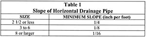
Table 1
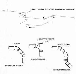
Figure 1
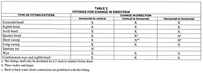
Table 2
Installation of the Building Drainage and Building Sewer System
Drainage piping installation must have uniform slope. The minimum desired velocity in a horizontal drainage pipe is approximately 2 feet per second. This velocity is often referred to as the "scouring velocity," even though such velocity might not always clean the walls of drainage pipe. The scouring velocity is intended to keep solids in suspension. For example, if the velocity is too low, where a drainpipe is excessively oversized, the solids tend to drop out of suspension, settling to the bottom of the pipe. This could eventually result in drain stoppage. A greater velocity is required to move solids at rest than is required to keep moving solids in suspension. A true scouring velocity would then be higher than the velocity initially used to transport solids. Table 1 provides the minimum recommended slope of horizontal drainage pipe.
Table 1. Slope of Horizontal Drainage Pipe
Size and Minumum Slope (inch per foot)
2-1/2 or less-1/4
3 to 6-1/8
8 or larger-1/16
A drainage pipe can be installed with greater slopes, and the slope is commonly expressed in percentages as total fall per length of pipe. For example, a 1% slope is approximately equivalent to 1/8-inch per foot and a 2% slope is approximately equal to 1/4-inch per foot.

Figure 2
One of the fundamental requirements of a drainage system is that the piping cannot be reduced in size in the direction of flow. A size reduction would create an obstruction to flow, possibly resulting in a backup of flow, an interruption of service in the drainage systems or stoppage in the pipe. In addition, horizontal branch connections to offsets and bases of drainage stacks must connect at a point located not less than 10 times the diameter of the drainage stack downstream from the stack. This phenomenon of flow can occur and is commonly called "hydraulic jump," which is the rising of the depth of flow above half full. To avoid flow interference, backup of flow and extreme pressure fluctuations, horizontal branch connections are prohibited in this area.
Sanitary drainage cleanouts are required to provide access to the drainage system for the purpose of clearing stoppages. They are intended to make the interior of the drainage system accessible for the cleaning of stoppages with relative convenience and without the costs and hardship involved with the cutting or dismantling of pipe and fittings. Cleanouts are typically required at the following locations: horizontal drains within buildings located not more than 100 feet apart; building sewers not more than 100 feet apart; and when a building sewer is 8 inches or larger, a manhole must be located at each change in direction and at intervals of not more than 400 feet; changes of direction of the building drain or horizontal waste or soil lines greater than 45 degrees (only one cleanout required for each 40 feet with more than one change of direction); and the building drain and sewer junction (see Figure 1).
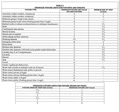
Table 3
Drainage Fittings
All connections and changes of direction of the sanitary drainage system must be made with approved drainage fittings based on the design patterns providing the least resistance to flow. Table 2 provides a table for approved drainage fittings based on the type of fitting pattern. The fitting standard defines the particular pattern for each piping material.
When the flow is in the horizontal plane only, long-pattern fittings are necessary to prevent excessive reduction in flow velocity. When flow is from the horizontal to the vertical, or from the vertical to the horizontal, a shorter pattern fitting may be used because the acceleration of flow due to gravity will maintain higher velocities. An "X" in the columns indicates that a particular fitting is acceptable for the described change in direction. The table has been developed to identify where a particular drainage pattern fitting is permitted. Note "a" permits the use of 2-inch or smaller short-sweep and quarter-bend fitting for drains serving a single fixture where the change in direction is from the vertical to horizontal or from the horizontal to horizontal. Note "b" permits the use of short-sweep fittings of 3 inches in diameter or larger where the change in direction is from the vertical to the horizontal.
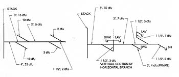
Figure 3
Sizing the Sanitary Drainage System
The sizing of drainage piping systems is based on fixture unit values. The fixture unit value takes into consideration the average rate of discharge, duration of use for a single operation and the interval between each operation of a plumbing fixture. A fixture unit should be considered a probability factor since there is no direct correlation to the discharge flow rate from a given fixture. Table 3 provides common fixture unit values for each plumbing fixture. Each fixture should be assigned a given fixture unit value when sizing the drainage piping system. For a private bathroom with fixtures intended for a single user, the grouping is assigned a single value under the bathroom group listing.
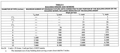
Table 4
The last column of Table 4 lists the minimum trap size required for the corresponding fixture. Minimum trap size is also the minimum drainage pipe size because a drainage pipe cannot be reduced in size in the direction of flow. Building drains are the lowest portions of the drainage system that drain horizontally by gravity. Building drains are sized in accordance with Table 4. The minimum size of each pipe section is based on the slope of the pipe and the number of dfu's that connect to that section (see Figure 2).
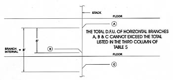
Figure 4
For horizontal branches, stacks three branch intervals or less in height and stacks greater than three branch intervals are sized in accordance with Table 5. This table is really two separate sizing tables, one for horizontal branches and one for stacks. To size a horizontal branch, only the first two columns of the table are used. The fixture unit value for a horizontal branch is lower than the permitted load for a building drain or building sewer. The reduced load capacity of a horizontal branch is intended to minimize the adverse effects caused by flow from a horizontal branch entering a stack (see Figure 3).
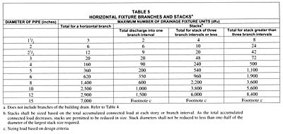
Table 5
To size a stack, there are three main criteria that must be considered: the discharge into a branch interval, total discharge into a stack and total number of branch intervals. Within any given branch interval, a stack is limited as to the maximum amount of discharge it can receive. A branch interval cannot be less than 8 feet and generally corresponds to a story height (see Figure 4). More than one horizontal branch is permitted to connect in a branch interval provided the total load for all branches is less than the dfu value listed in the two columns of the stack sizing table or the third column of Table 5 (see Figure 5).

Figure 5
In conclusion, these are the basic components of a sanitary drainage system that the design professional must take into consideration when designing a drainage system. The designer needs to understand that plumbing engineering is not an engineered science, as we know it. It relies on design experience, innovation and the proper use of codes and standards.
