For the design of the system, NFPA Code 2001, "Standard on Clean Agent Fire Extinguishing Systems" is followed. The Code recommends that the system be designed by a qualified clean agent extinguishing system designer. This sometimes indirectly means the agent supplier's authorized system designer.
The Scope of the Design
FM 200 design includes determination of the agent quantity, piping layout, pressure drop through the piping and accessories, as well as fixing the location and quantities of discharge nozzles for uniform distribution of the agent throughout the space. This also includes determining the filling density in the agent cylinders to take care of the pressure drop through the system, for determining the number of cylinders.From above, the agent quantity required for total flooding of the space is determined independently based on the design concentration of the agent necessary for the type of fire to be extinguished, Hold Time for extinguishing the fire, additional quantity required to take care of the leakage, etc.
Tentative pipe sizing and pipe routing with nozzle location are done by the owner or the engineer in harmony with the other facilities in the space. This is, however, finalized by the agent supplier's authorized system designer based on the pressure drop software program for two-phase flow of the agent. To take care of the system pressure drop and to establish the required pressure at the nozzles, the authorized agent determines the agent fill density in the cylinder. They also finalize the number of cylinders based on the fill density and their standard cylinder size.
Protected Areas
The areas to be protected are identified from the fire risk analysis of the plant and the various codes (like NFPA, etc). The requirements are guided by the functional criticality of the system protected, amount of loss involved, fire insurance premium, etc.
Design Philosophy
A typical case of protecting a power station using the FM 200 total suppression system is the basis for the following design information. Design Code: NFPA 2001, "Clean Agent Fire Extinguishing System," is the governing code for designing the system, and NFPA 72, "National Fire Alarm Code," is followed for fixing the fire alarm system, an important part of the clean agent total suppression system. Agent Concentration: Since FM 200 is the most expensive item of the total system, a careful analysis is required before fixing the required concentration and the total quantity of the agent.Regarding design concentration of the agent, there are various guidelines available, such as:
* 120% of cup burner value verified by listing/approval tests, minimum design concentration (%V/V) of FM 200 is 7%, (refer to Table 4-7.5 Weight and Storage Volume Equivalent data for New Technology Halocarbon Gaseous alternatives' SFPE Handbook on Fire Protection Engineering).
- The same agent concentration of 7% is accepted by Factory Mutual (FM) as the design agent concentration.
- Underwriters' Laboratories (UL), however, recommends the agent design concentration as 7.44%.
To satisfy both FM and UL, it seems prudent to consider the design concentration as 7.44% by volume. The FM 200 supplier's authorized agent normally recommends 7% as the design concentration, based on their experience with the type of fire anticipated in the areas protected. Increase of the agent concentration from 7% to 7.44% has the repercussion on the cost of the agent. If possible, the recommendation of the AHJ (Authority of Jurisdiction) should be solicited before fixing the agent design concentration.
The maximum limit of the FM 200 concentration is restricted by NFPA 2001 due to the safety considerations of the toxicological and physical effects on human life.
NFPA 2001 Clause a-1-5.1.2 recommends the following concentration level of FM 200 in the protected compartment:
- No Observable Adverse Effect Level (NOAEL)-Concentration of 9% and below (%V/V)
- Lowest Observable Adverse Effect Level (LOAEL)-Concentration above 10.5% (%V/V).
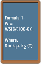
Agent Quantity: The formula mentioned in Clause 3.5.1 of NFPA 2001 is used for preliminary quantity calculation of the agent requirement. The formula is as follows:
Where:
W = Weight of Clean Agent, lb./ft.
T = Minimum anticipated temperature of the protected volume, degrees F.
k1 and k2 = constants specific to the clean agent being used (FM 200), the values of which are to be taken from Table 3-5.1 (a) of NFPA 2001.
C = FM 200 design concentration, % by volume. As we've already discovered, C = 7.44%.
V = Volume of the hazard.
S = k1 and k2 (T) is a linear equation determined by least squares curve fit techniques from data supplied by the clean agent manufacturers. The zero concepts are k1 and the slope is k2.
Hazard volume ("V") in the above formula is the volume of the room protected. Sometimes the volume occupied by the hvac ducting inside the room up to the first isolation damper is added to the room volume, when the room is provided with a suspended ceiling and the duct is running in the space above the suspended ceiling.
Regarding the selection of the temperature inside the protected area, the NFPA recommends the minimum anticipated temperature. The authorized system designer normally takes into consideration the prevalent temperature inside the rooms, which are air-conditioned. The agent quantity requirement increases with the lower temperature of the protected volume. However, during an abnormal condition, such as the plant being under maintenance, when the hvac system is not running, the room's indoor temperature may attain the minimum outdoor temperature. It is therefore prudent to consider the minimum outdoor temperature prevalent from the climatological data and not the minimum design temperature specified for other equipment selection as the minimum anticipated temperature for agent calculation.
To extinguish the fire effectively, the design agent concentration is to be retained inside the room for a period called "Hold Time." During the Hold Time, the air-agent mixture is expected to leak in case the enclosure is not made perfectly leak-tight. So, to maintain the design concentration up to the end of Hold Time, the agent quantity derived per Formula 1 is jacked up by the expected leakage quantity to initially discharge the higher quantity of agent than required for the design concentration. This will effectively increase the initial agent concentration more than the design concentration (7% or 7.44%). The initial agent concentration, however, will come down to the design concentration due to the leakage of the agent throughout the period of Hold Time.
Agent Leakage and Effect of Altitude: Leakage of the agent from the enclosure is an important issue for maintaining the desired agent concentration inside the enclosure during the Hold Time required for extinguishing the fire.
Total FM 200 flooding within a short period of 10 seconds will suddenly raise the pressure inside the room due to the agent's expansion. The sudden rise in pressure will, however, die down to normal room pressure within a short period at the quiescent state. Therefore, there is the possibility of leakage at the time of discharge and also during the quiescent state due to the heavier air-agent mixture in the room compared to the air outside.
Leakage due to expansion at the time of discharge is included in Formula 1 in calculating the initial agent quantity per NFPA 2001. (The calculation includes an allowance for the normal leakage from a "tight" enclosure due to agent expansion.) Thus, any leakage from the sudden expansion of FM 200 at initial discharge is not considered further for a tight enclosure, which does not have any large opening that is difficult to seal.
During the quiescent state, due to the difference in density between the FM 200 air mixture inside the room and the air outside the room, the FM 200 and air mixture will leak out of the room through the leakage area. Per NFPA recommendations, room height is considered as the static head for the leakage.
To be more precise, the leakage rate is determined by the Door Fan Pressurization Test, as recommended by NFPA 2001. Like during the design stage, such leakage value cannot be arrived at by the Door Fan test; the leakage rate is estimated based on the probable leakage areas, such as leakage through the door gaps, damper gaps, tiles of the raised floor, etc.
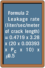
Leakage Through Door Gaps: It is prudent to calculate the leakage rate through the door gaps from the ASHRAE (American Society of Heating, Refrigerating and Air-conditioning Engineers) formula, as follows:
Where:
Pc = g x H0 x (rm - ra), per Equation 1 Clause B-2.6.1.3 of NFPA 2001.
g = Acceleration due to gravity
rm = FM 200 and air mixture density, kg/m3. Refer to NFPA 2001 Clause B-2.7.1.4.
ra = Air density, kg/m3.
H0=Height of ceiling, m.
Leakage Through Raised Floor Tiles: The leakage by diffusion through the tiles of the raised roof floor is considered only when the raised floor of the room in isolation is protected by FM 200. When both the room and the raised floor are protected by FM 200, such leakage through the raised floor is not to be considered, as the agent is discharged simultaneously to both the room and its raised floor from the fire signal from either of the spaces.
Leakage Through Wall Penetration: Penetration for cable raceways and piping through the firewall is sealed to achieve the most perfect leak tightness as possible and restrict any leakage through the penetration sealing.
Leakage Through Damper Gaps: Dampers are placed in the hvac ducts, which are routed near the ceiling of the enclosed volume. As such, during the quiescent state, the static height responsible for leakage due to difference in density between the air-agent mixture and the air outside should be the diameter for the round duct or height for the rectangular duct. To simplify, for practical purposes, the same static head, i.e. the height of the room, is considered for leakage quantity determination through the damper. For estimation purposes, a crack width of 0.0016 mm (same as door) can be considered around the perimeter of the duct to get the leakage area for the damper. Leakage to Suspended Ceiling: It depends upon the type of fixtures used on the suspended ceiling. Normally, the suspended ceiling is made from a number of panels connected together by clips through which the leakage is not expected. With the ceiling on the top, there is no static height of the air-agent mixture for leakage at the quiescent state.
Effect of Altitude: At elevations above sea level, FM 200 expands to a greater specific vapor. A system designed for sea level will develop a greater concentration level at higher altitude. To correct for the effects of a higher elevation, the quantity of the agent is reduced by a factor available in the catalog cuts of the authorized system designer.
Agent Hold Time: This is the time required to hold the agent inside the enclosure at its desired concentration until the fire is extinguished. The Hold Time, which is contingent to the type of fire, items under fire, extent of fire, etc., is generally dictated by the AHJ, probably based on the statistical data or experiments.
For practical purposes, such values are not usually available when the design of the system is prepared. NFPA 2001 Clause B-2.7 for Retention Time can be followed to estimate the Hold Time.
In Clause B-2.7.1.7, NFPA 2001 gives a formula for calculating the time required to maintain the descending interface level of air agent mixture at or above the height required for minimum agent concentration in the room. The interface level of the air agent mixture descends due to the leakage of the agent from the enclosure. Per Clause B-2.7.2 of NFPA 200a, this time can be considered as the Hold Time when no definite value of the same is available.
The NFPA formula for calculating Hold Time is as follows:
Where:
t = Time, sec. The enclosure is expected to maintain the descending interface above H for the time t. This is the maximum Hold Time expected for the hazard.
C3 = Constant for equation simplification.
C4 = Constant for equation simplification.
AR = Room floor area, m2.
AT = Total leakage area, m2.
g = Acceleration due to gravity, 9.81 m/sec2.
PSH = Static Pressure during discharge, Pa.
PSH = 0.25 PC, max. Refer to NFPA 2001 Clause B-2.5.2.3.
PC = Pressure due to the agent column (density difference), Pa.
PC = g H0 (rm - ra). Refer to NFPA 200a Clause B-2.6.1.3.
rm = FM 200 and Air mixture density, kg/m3. Refer to NFPA 2001 Clause B-2.7.1.4.
ra = Air density, kg/m3.
H0 = Height of ceiling, m.
H = Height of interface from floor, m.
H = H0 (CF/C). Refer to Clause B-2.7.1.6 of NFPA 2001.
CF = Final agent concentration, 7.44 % (assumed, as mentioned previously, to maintain the design concentration for extinguishing the fire).
C = Initial agent concentration, as derived from the total quantity of FM 200 discharged in the volume protected.
In any case, the Hold Time should not be less than ten (10) minutes, which is a traditional generic value to extinguish the fire.
