For decades, most boilers used in North America had large internal fluid passages and exhibited very low flow resistance. When these boilers were combined with generously sized supply and return headers, the overall flow resistance of the “common piping” was low enough that several zone circulators could operate simultaneously with very little interference (seeFigure 1).
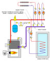
Figure 1
The traditional remedy to this situation has been the use of primary/secondary piping. The high flow resistance boiler is set up on its own secondary circuit, as shown inFigure 2.
The distribution system is configured as a parallel primary loop. The closely spaced tees in each crossover provide hydraulic separation between each of the circuits. The parallel configuration of the crossovers ensures equal supply temperature to each secondary circuit.

Figure 2
Consider a system that supplies 500,000 Btu/hr to a compact parallel primary loop at design load conditions. The common piping in the primary loop is 2-inch copper, and the five crossovers are 1-inch copper with balancing valves. Design flow in the common piping of the primary loop is 50 gpm with a relatively small corresponding head loss of 3.4 feet (1.44 psi pressure drop). Assume a wet rotor circulator with wire-to-water efficiency of 25% is used as the primary circulator in this system.


This, combined with the installation cost of the circulator and additional piping hardware associated with the parallel primary loop, is not a trivial portion of the system’s life-cycle cost.
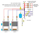
Figure 3
Numerous Alternatives
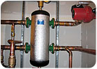
The schematic inFigure 3shows one way to retain the benefits of hydraulic separation as well as equal supply temperatures to the load circuits without use of a parallel primary loop and its associated circulator.The boilers are connected to a large-diameter vertical header within a relative compact space. Boiler piping is hydraulically separated from the vertical header using a pair of closely spaced tees. The generous diameter of the header and relatively close spacing between all supply and return connections results in a very low pressure drop between points A and B-low enough that each load circuit is effectively hydraulically separated from the others.
The header should be sized for a maximum flow velocity of 2 feet per second with all load circulators operating.Its length should also be kept as short as possible. If the header is installed vertically (as shown inFigure 3), include a float-type air vent at the top and a drain at the bottom. The latter allows sediment returned from the load circuit to accumulate at the bottom where it can be periodically flushed out. Because the load circulators are in parallel and connected to a common header, each circuit must include a check valve (internal to circulator or external) to prevent flow reversal through inactive zone circuits.
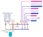
Figure 4
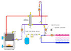
Figure 5

Figure 6.
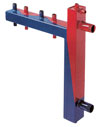
Figure 7.
The number of companies offering hydraulic separators in North America also is growing.Figure 8andFigure 9show the use of a hydraulic separator in a large industrial radiant floor heating system in the Northeast.
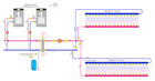
Figure 8
Figure 9.
Back To the Future
One might look to the time when cast-iron and steel fire-tube boilers were used in the vast majority of North American hydronic systems and conclude that we’ve been relying on hydraulic separation for decades. Few of us, including the author, used the words hydraulic separation to describe the physics at work in these traditional systems. Perhaps we just assumed that circulator interference and flow bottlenecking at the boiler were “nonproblems.”As boilers with higher flow resistance entered the market and complex multiload systems were designed around traditional piping schemes, the lack of hydraulic separation taught us some valuable lessons. The industry’s overall response was to turn to primary/secondary piping as a means of reestablishing the hydraulic separation provided in traditional systems. Although this approach works, it requires an extra circulator and additional piping components.
Figure 10

